Instruction Formats and Addressing Modes for GATE: One Cross-Concept COA Problem Solved
Decode one teaching instruction from 0x2E35FFEC, calculate its effective address, read the little-endian value, and trace the result through a five-stage pipeline.
KnowledgeGate Team
Exam prep & CS education
Updated 15 Sep 20266 min read
A COA question may give an instruction word in hexadecimal, ask for its field values, require an effective address, and then ask what happens in memory or the pipeline. These tasks form one dependency chain: the bit layout determines the addressing calculation, which determines the memory read and final pipeline effect. Under the teaching ISA, 0x2E35FFEC traces to the value loaded into R3.
Instruction formats and addressing modes: one chain, not separate chapters
The dependency starts with instruction width. It fixes the total bit budget. Field widths then determine which values can be encoded, mode bits decide how the operand field is interpreted, effective-address logic selects a memory location, and the operation determines the final register and memory activity.
Format and meaning are different. An instruction format answers, "Where are the bits?" An addressing mode answers, "How do these bits locate or represent an operand?" The same 16-bit field might be a signed displacement, a direct address, an immediate value, or an ignored field under different mode codes.
Use the GATE CS Exam Preparation Courses & Test Series page for broader preparation context. For address-count formats, expanding opcodes, and a six-mode survey, use Instruction Formats and Addressing Modes in COA: Complete Guide with Worked Examples; Computer Instruction Explained: Format, Instruction Cycle and a 16-Bit Worked Example traces a shorter 16-bit positive-displacement load. The 32-bit problem below adds field budgeting, a negative displacement, little-endian assembly, and five pipeline stages to the same dependency chain.
COA field budgeting: derive the 32-bit teaching format
All field widths, mode meanings, and calculations belong to a made-up teaching ISA, not a real processor ISA. It has fixed 32-bit instructions, 32-bit byte addresses, 64 opcodes, 4 addressing modes, and 16 general-purpose 32-bit registers. A load needs one destination register Rd, one base register Rb, and one displacement or address field.
The widths follow from the number of choices:
Opcode:
ceil(log2 64) = 6bitsMode:
ceil(log2 4) = 2bitsRd:ceil(log2 16) = 4bitsRb:ceil(log2 16) = 4bits
These fields consume 6 + 2 + 4 + 4 = 16 bits. The remaining width is 32 - 16 = 16 bits, so call it disp16. The fixed layout is bits [31:26] opcode, [25:24] mode, [23:20] Rd, [19:16] Rb, and [15:0] disp16. As a 16-bit two's-complement number, disp16 ranges from -32768 to 32767.
Addressing-mode rules: turn fields into operands or addresses
This teaching ISA assigns four meanings to the mode field:
Mode | Meaning | Operand or effective address |
|---|---|---|
| Immediate | Operand = |
| Direct |
|
| Base plus displacement |
|
| Register indirect |
|
Keep the encoded field, effective address, and stored value separate. For a load, disp16 = 0xFFEC is not the loaded data. The computed EA = 0x000011EC is also not the data. It is the address from which the data is read.
Assume LOAD = 001011 only for this teaching machine. A real question must supply or imply its own opcode and mode table. These binary codes are not universal.
Fully worked decode: 0x2E35FFEC becomes LOAD R3, -20(R5)
First expand the 32-bit word according to the fixed boundaries:
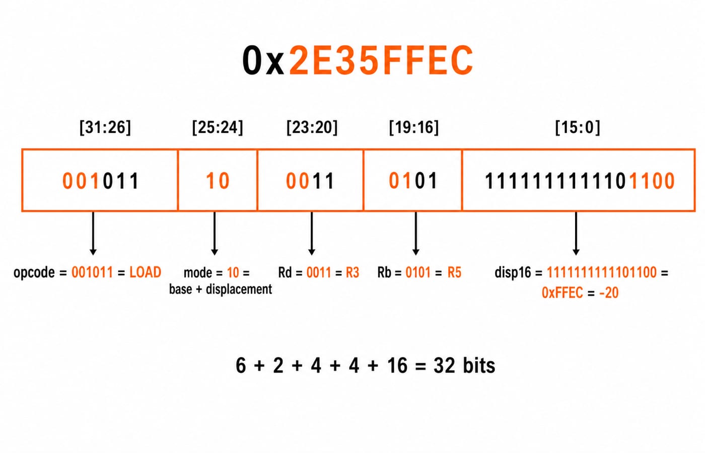
0x2E35FFEC = 001011 10 0011 0101 1111111111101100
The fields decode as follows: 001011 is LOAD, 10 is base plus displacement, 0011 is R3, 0101 is R5, and 0xFFEC is the signed 16-bit displacement.
To decode its sign, invert 0xFFEC to get 0x0013, then add 1. The magnitude is 0x0014 = 20, so the displacement is -20.
Now fix R5 = 0x00001200. Sign extension preserves the negative value:
sign_extend(0xFFEC) = 0xFFFFFFEC
Therefore, in 32-bit arithmetic:
EA = 0x00001200 + 0xFFFFFFEC = 0x000011EC
The decimal-offset cross-check gives the same result: 0x1200 - 0x14 = 0x11EC.
Suppose addresses 0x000011EC through 0x000011EF contain bytes 20 10 3C 7A. Because the machine reads them in little-endian order, the first byte is least significant. The 32-bit word is 0x7A3C1020, so the architectural effect is R3 <- 0x7A3C1020.
Result item | Value |
|---|---|
Encoded word |
|
Opcode |
|
Mode |
|
Registers |
|
Signed displacement |
|
Effective address |
|
Memory bytes |
|
Final |
|
Instruction execution trace: from fetch to register write-back
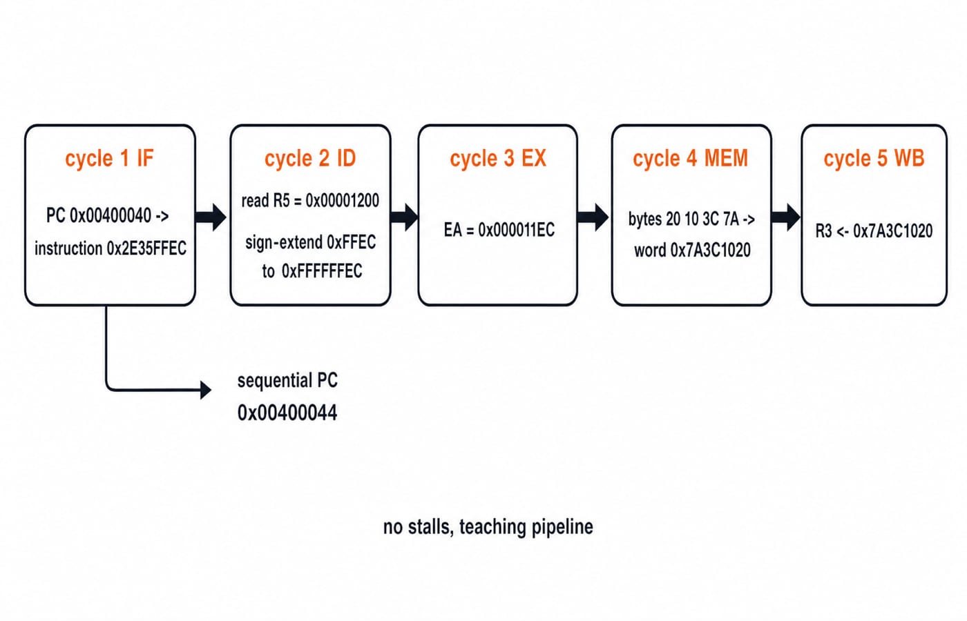
Place the instruction at aligned PC = 0x00400040. A fixed four-byte instruction makes the sequential next PC 0x00400044. In a classic five-stage teaching pipeline with no stalls, the trace is:
Cycle 1,
IF: fetch0x2E35FFEC.Cycle 2,
ID: decode the fields and readR5.Cycle 3,
EX: computeEA = 0x000011EC.Cycle 4,
MEM: read bytes20 10 3C 7A.Cycle 5,
WB: write0x7A3C1020toR3.
This isolated load makes exactly two logical memory references under the stated model: one aligned instruction fetch and one aligned 32-bit data read. Register-file reads and writes are not main-memory references. The displacement is already inside the instruction, so using it causes no extra reference.
Pipelining in Computer Architecture: Speedup and Hazards develops the wider timing model. These two logical references still do not determine cache hits or misses without line size, mapping, initial contents, and replacement assumptions.
Cross-concept variants: change one rule and recompute the answer
Change the mode to direct 01 while keeping the low 16 bits. Now EA = zero_extend(0xFFEC) = 0x0000FFEC, and Rb = R5 is ignored. Under base plus displacement, the result was 0x000011EC. The field stayed fixed, but the mode changed its meaning.
Next, make the common sign-extension mistake. If 0xFFEC is wrongly zero-extended under base plus displacement, the false calculation is 0x00001200 + 0x0000FFEC = 0x000111EC, not 0x000011EC.
Finally, grow the register set from 16 to 32. Each of the two register fields now needs ceil(log2 32) = 5 bits. With the instruction, opcode, and mode widths unchanged, the displacement shrinks to 32 - 6 - 2 - 5 - 5 = 14 bits.
GATE cross-concept traps and question patterns
Watch for these errors:
Counting hexadecimal digits as bits instead of expanding each digit to four bits
Forgetting that
RdandRbconsume separate fieldsTreating signed
0xFFECas positive65516Confusing the effective address with the value loaded from memory
Counting register-file activity as main-memory access
Inferring cache misses when no cache model is supplied
Exam variants may hide a field width, present the instruction in hexadecimal, change the mode code, or ask for the final register value after a memory read. The KnowledgeGate practice bank currently offers over 60 questions in its mixed instruction-formats-and-modes topic.
For official question-format labels and their definitions, consult the GATE 2026 question paper pattern. It is the authority for those format specifics. The teaching ISA and calculations here stand on the assumptions stated in the problem, not on an official paper pattern.
Instruction formats and addressing modes: the short version
Use six steps: budget the fields, split the word, decode each field, apply the selected mode, compute the effective address, and trace the data movement. Here the complete chain is 0x2E35FFEC -> LOAD R3, -20(R5) -> EA 0x000011EC -> R3 0x7A3C1020.
If you need repeated subject-wise and mixed-concept practice under a structured flow, use the GATE Test Series as the next step.
Keep learning

Multiprocessor Classification: Flynn Taxonomy, Memory Models and Exam-Style Worked Examples
Learn how to choose the right multiprocessor classification axis, then solve a four-lane SIMD trace and a NUMA average-access-time problem step by step.
Updated 27 Sep 20266 min readComputer Organization & Architecture

Interrupt-Driven I/O Explained: CPU Handshake, Worked Timing Example and GATE Traps
Trace an interrupt from device request to return-from-interrupt, then compare polling, per-event interrupts, and DMA through worked timing examples.
Updated 25 Sep 20267 min readComputer Organization & Architecture
Interface Addressing Explained: Memory-Mapped vs Isolated I/O with Worked Examples
Understand what an interface address selects, how memory-mapped and isolated I/O differ, and why partial decoding creates multiple addresses for the same register.
Updated 23 Sep 20266 min readComputer Organization & Architecture
Instruction Structure in Computer Organization: Fields, Encoding and Exam Problems
Learn how opcode, register, mode and displacement fields divide an instruction word. Follow checked examples for address forms, decoding and expanding opcodes.
Updated 22 Sep 20265 min readComputer Organization & Architecture