Interrupt-Driven I/O Explained: CPU Handshake, Worked Timing Example and GATE Traps
Trace an interrupt from device request to return-from-interrupt, then compare polling, per-event interrupts, and DMA through worked timing examples.
KnowledgeGate Team
Exam prep & CS education
Updated 25 Sep 20267 min read
Polling is easy to picture, but interrupt-driven I/O becomes blurry at the exact point where normal execution stops. What state does the processor save, and why can an interrupt use less CPU time? A hardware I/O request moves from device signaling through CPU service and back to the interrupted program; polling and interrupts differ in CPU cost, while DMA suits sustained bulk transfer.
Interrupt-driven I/O: the idea and the hardware boundary
In interrupt-driven I/O, the CPU starts an I/O operation and continues executing useful instructions. When the device is ready, its controller sets the relevant status and asserts an interrupt request. The CPU responds when it reaches an allowed interrupt boundary.
The participating pieces are the CPU, device controller, status and data registers, interrupt-request line, interrupt-acknowledge signal, interrupt vector or identification logic, and an interrupt service routine (ISR). This mechanism is part of the broader GATE CS exam-preparation syllabus.
Programmed polling works differently. The CPU repeatedly reads a ready bit, even while nothing has changed. With interrupts, the controller changes the ready state and raises a request. The ISR may still use CPU instructions to move data through a device register, so interrupt-driven does not mean no CPU work.
What the controller's status and control registers look like on the far side of that boundary, exact addresses, exact bit fields, and the read-to-clear rule that ends an event, is traced in Computer Interfaces in COA, which also carries this series' single numeric CPU-occupancy comparison across all three transfer modes.
Interrupt-driven I/O sequence: request, ISR and return
The usual request-to-return path is:
The CPU issues an I/O command, and the controller begins work.
The device becomes ready. The controller sets READY and asserts IRQ.
The CPU normally completes its current instruction, then checks interrupt enable, masking, and priority.
The CPU acknowledges the accepted request.
Hardware and/or the ISR saves enough return state. The source or vector selects the ISR.
The ISR transfers data, clears or acknowledges the cause, restores state, and executes return-from-interrupt (RTI).
The interrupted program resumes.
The exact saved registers depend on the architecture, but the next program counter and processor status must be recoverable.
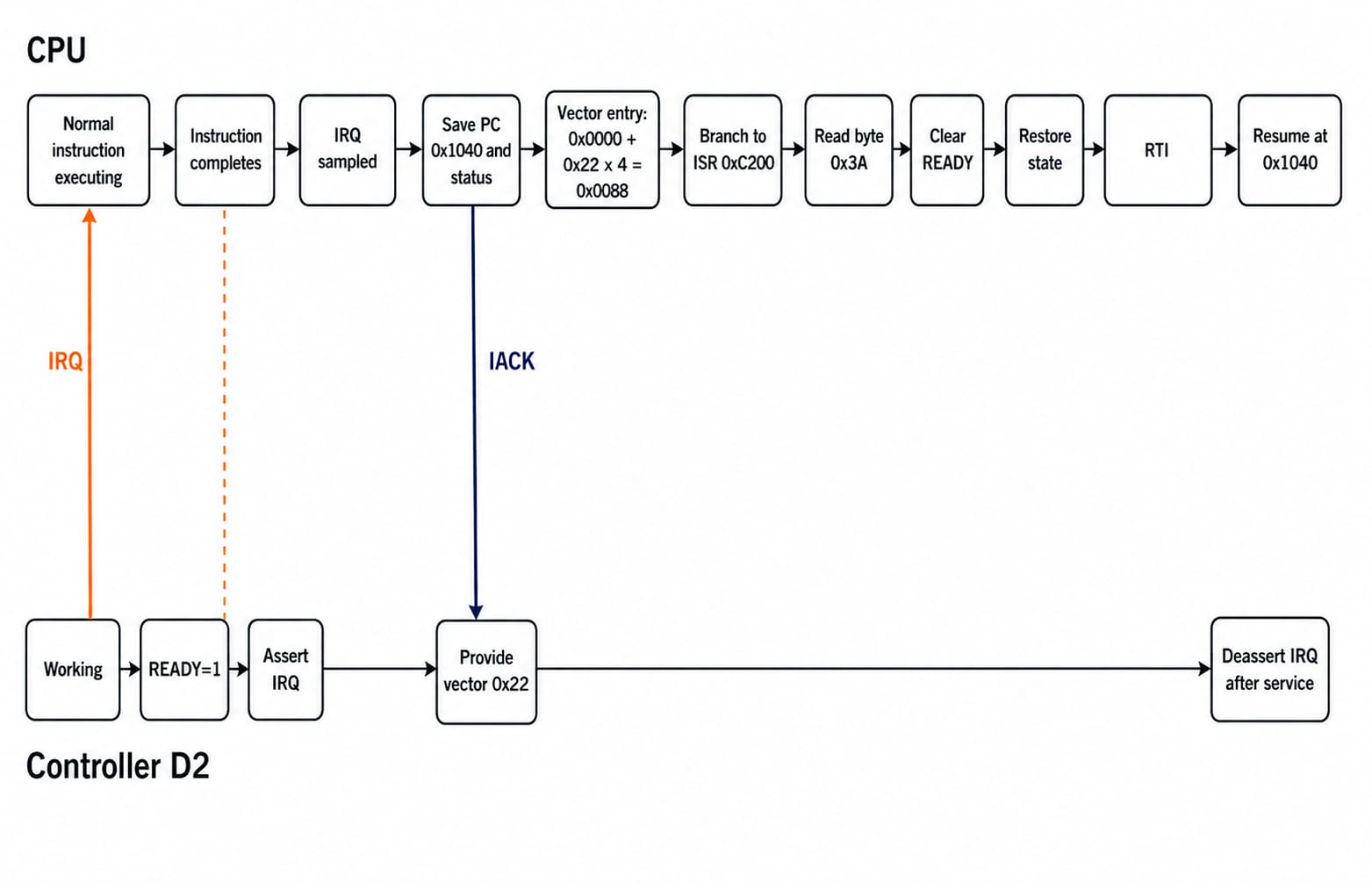
Consider a fictional machine. Device D2 raises IRQ while the CPU executes the instruction before PC = 0x1040. Once that instruction finishes, the saved return PC is 0x1040, the address of the next instruction. Readers who want to revise that instruction context can use Addressing Modes and Instruction Formats.
D2 supplies vector 0x22. The vector-table base is 0x0000, and each entry occupies 4 bytes, so the entry address is 0x0000 + 0x22 × 4 = 0x0088. That entry contains ISR address 0xC200. The ISR reads data byte 0x3A, clears READY, restores status and PC, and RTI resumes at 0x1040. These addresses define this example, not a universal architecture.
Interrupt classes, vectoring and priority
A vectored interrupt supplies or implies a selector for an ISR or vector-table entry. A non-vectored interrupt goes to a common location, after which hardware or software identifies the source. Vectoring does not eliminate every possible arbitration step, and non-vectored designs do not necessarily poll every device in software.
A maskable interrupt can be postponed by masking. A correctly latched pending request is delayed, not erased. A non-maskable request is reserved for events that the normal mask should not postpone. Priority decides which eligible pending request is accepted first. Higher-priority work can delay a lower-priority ISR, while excessive masking can let a device buffer overrun.
For a daisy chain ordered D0, D1, D2, D3 from nearest to farthest from the CPU, D0 has the highest hardware priority. If D2 and D3 request together while D0 and D1 are idle, the acknowledge passes through D0 and D1. D2 captures it, and D3 waits. The physical chain order establishes priority here, not the device number by itself.
Interrupt-driven I/O worked example: CPU time versus polling
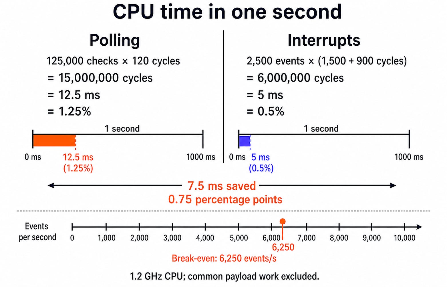
Assume a 1.2 GHz CPU (1,200,000,000 cycles/s) and a device that becomes ready 2,500 times per second. Polling checks the status register every 8 microseconds at 120 cycles per check. Interrupt entry plus exit costs 1,500 cycles, and ISR control costs 900 cycles per event. Payload-processing cycles are identical and excluded. Assume no coalescing and no missed requests. These cycle counts and rates define this example, not universal hardware.
Polling consumes:
1 second / 8 microseconds = 125,000 checks
125,000 checks × 120 cycles per check = 15,000,000 cycles
At 1.2 GHz, 15,000,000 cycles = 12.5 ms, which is 1.25% of one second
Interrupt control consumes:
(1,500 + 900) cycles per event × 2,500 events = 6,000,000 cycles
At 1.2 GHz, 6,000,000 cycles = 5 ms, which is 0.5% of one second
Interrupts save 12.5 - 5 = 7.5 ms of CPU time per second. They reduce control overhead by a factor of 12.5 / 5 = 2.5 and improve the available CPU share by 1.25% - 0.5% = 0.75 percentage points.
The polling design always spends 15,000,000 control cycles per second. Each interrupt event costs 2,400 cycles, so break-even is 15,000,000 / 2,400 = 6,250 events per second. Below that rate, this interrupt design has lower control overhead. Above it, the arithmetic reverses, but batching or DMA is usually a better response to a sustained bulk stream than blindly increasing the polling rate.
Polling, interrupt-driven I/O and DMA: choose by workload
Mechanism | Who notices readiness | Who moves data | CPU control cost | Best fit | Main risk |
|---|---|---|---|---|---|
Polling | CPU reads status | CPU instructions | Repeated checks | Short, predictable waits or simple controllers | Wasted CPU time while waiting |
Interrupts | Controller raises IRQ | Often CPU instructions in ISR | Entry, ISR and exit per event | Sporadic, moderate-rate events | Interrupt storms, latency or overrun |
DMA | DMA controller signals coarse progress or completion | Controller transfers between device and memory | Setup, arbitration and coarse interrupts | Large blocks or sustained streams | Setup cost and bus contention |
When the answer is DMA, the controller's own address and count registers, and the difference between burst and cycle-stealing bus ownership, are worked through in Direct Memory Access (DMA) Explained. This post stops where the CPU stops being involved.
The scale difference becomes clear for a 3 MiB block at 12 MiB/s. Transfer time is 3 / 12 = 0.25 s. The block contains 3,145,728 bytes. If the CPU takes one interrupt per 4-byte word, it receives 3,145,728 / 4 = 786,432 interrupts. At 2,400 cycles of interrupt control each, that is 786,432 × 2,400 = 1,887,436,800 cycles, or 1.572864 s at 1.2 GHz. CPU control time alone would need more than six times the 0.25 s the stream takes to arrive. It cannot keep up. Block DMA reduces this to setup plus a completion interrupt, although DMA still needs bus arbitration. These transfer values define this scale example, not universal hardware.
For the topic map, interface registers, memory-mapped versus isolated addressing and DMA cycle stealing in one place, use Input Output Organisation in COA. This post instead hinges on request acceptance, saved return state, vectoring, daisy-chain priority, ISR return and the polling break-even rate.
Interrupt-driven I/O exam patterns and common traps
The official GATE 2026 Computer Science and Information Technology syllabus places “I/O interface (interrupt and DMA mode)” under Computer Organization and Architecture. That is a scope statement for the 2026 syllabus, not a claim about marks, frequency, or a future exam cycle.
Interrupt handling must account for instruction boundaries and priority, while DMA suits high-throughput block transfers.
A precise maskable IRQ arrives halfway through an instruction. In the model used here, the CPU completes that instruction before entering the ISR. Some architectures include restartable or imprecise cases, so apply the architecture stated in the question.
Two interrupt sources are pending. A vector identifies the ISR or vector-table entry. Priority decides which eligible source is accepted first.
A disk sends a high-throughput block to memory. DMA is suitable because an interrupt for every word creates excessive CPU control overhead.
Common traps are equally direct. An interrupt is a notification, not the data itself. Saving general registers while losing PC or status cannot support a correct resume. Interrupt latency is the delay before service begins, not the ISR's execution time. Masking is not priority, and interrupts are not automatically cheaper than polling at every event rate.
Interrupt-driven I/O: the short version and next step
The controller raises a request.
The CPU accepts it at an allowed boundary.
The return state is preserved.
Vectoring and arbitration select the service routine.
The ISR handles the device and clears the cause.
RTI restores the interrupted program.
Use polling for tiny, predictable waits, interrupts for sporadic readiness, and DMA for blocks. If you are preparing the wider syllabus, GATE Guidance by Sanchit Sir provides a structured route through GATE CS topics.
Without looking back: for the 1.2 GHz worked example, why is the break-even rate 6,250 events per second, and what assumption makes that number model-specific?
Keep learning
Multiprocessor Classification: Flynn Taxonomy, Memory Models and Exam-Style Worked Examples
Learn how to choose the right multiprocessor classification axis, then solve a four-lane SIMD trace and a NUMA average-access-time problem step by step.
Updated 27 Sep 20266 min readComputer Organization & Architecture
Interface Addressing Explained: Memory-Mapped vs Isolated I/O with Worked Examples
Understand what an interface address selects, how memory-mapped and isolated I/O differ, and why partial decoding creates multiple addresses for the same register.
Updated 23 Sep 20266 min readComputer Organization & Architecture
Instruction Structure in Computer Organization: Fields, Encoding and Exam Problems
Learn how opcode, register, mode and displacement fields divide an instruction word. Follow checked examples for address forms, decoding and expanding opcodes.
Updated 22 Sep 20265 min readComputer Organization & Architecture
Disk Structure and Disk Addressing for GATE: CHS, LBA and Worked Examples
Use one consistent disk geometry to connect platters, surfaces, tracks and sectors with capacity, CHS-to-LBA conversion, address width and access time.
Updated 21 Sep 20265 min readComputer Organization & Architecture