Instruction Formats and Addressing Modes in COA: Complete Guide with Worked Examples
Learn how zero, one, two, and three-address instructions change a program, then solve expanding-opcode and effective-address questions step by step.
KnowledgeGate Team
Exam prep & CS education
Updated 21 Aug 20266 min read52 views
You can draw a CPU block diagram yet still freeze when a question asks how many one-address instructions remain encodable or what an indirect instruction fetches. Both come from the same concepts: instruction formats and addressing modes. Treat an instruction as a bit budget and each mode as a formula, and every answer becomes computable.
Anatomy of an instruction: opcode, operand fields, and address count
An instruction carries an opcode for the operation, plus operand or address fields for the locations it needs. Many formats spend a few more bits on addressing-mode bits; the 16-bit example below does not, so every bit goes to the opcode and the addresses. Instruction length is a fixed budget. More address fields make it longer or leave fewer bits for every field.
The classic families differ by the number of explicit addresses:
Three-address:
ADD R1, A, Bkeeps both sources and writes a separate result.Two-address: one named operand also receives the result, so a source is overwritten.
One-address: the accumulator is implicit. The instruction names only the other operand.
Zero-address: a stack supplies both operands implicitly.
Fewer explicit addresses usually mean shorter instructions, but more instructions are needed to complete a calculation.
Worked example A: one expression, four instruction formats
Evaluate X = (A + B) * (C + D).
Three-address format, 3 instructions
ADD R1, A, B
ADD R2, C, D
MUL X, R1, R2
Two-address format, 6 instructions
MOV R1, A
ADD R1, B
MOV R2, C
ADD R2, D
MUL R1, R2
MOV X, R1
One-address accumulator format, 7 instructions
LOAD A
ADD B
STORE T
LOAD C
ADD D
MUL T
STORE X
Zero-address stack format, 8 instructions
PUSH A
PUSH B
ADD
PUSH C
PUSH D
ADD
MUL
POP X
The counts grow from 3 to 6 to 7 to 8 as explicit addresses fall. The stack sequence evaluates the postfix expression A B + C D + *, a pattern reused in expression-evaluation questions. The architectural side of the same classification, including why fixed-length encoding suits RISC decoding and variable-length encoding suits denser CISC code, is worked through in addressing modes and instruction formats in computer architecture.
Instruction-length arithmetic: an expanding-opcode example
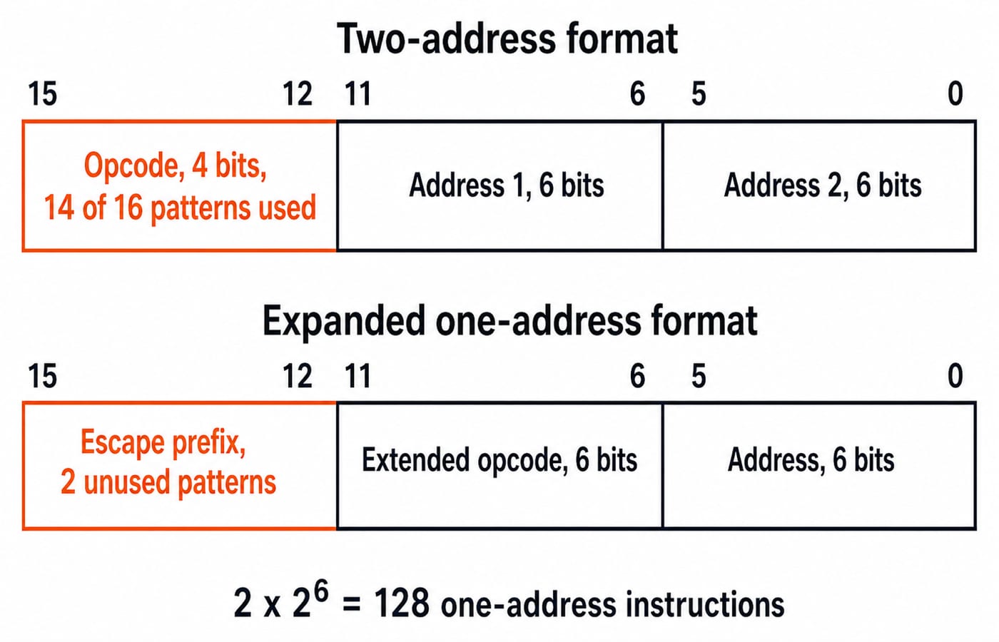
Suppose a machine has 16-bit instructions and 6-bit address fields. A two-address instruction uses:
4-bit opcode + 6-bit address + 6-bit address = 16 bits
Four opcode bits provide 2^4 = 16 possible two-address opcodes. Now suppose the ISA uses only 14. The remaining 2 patterns can act as escape prefixes for one-address instructions. Removing one 6-bit address field frees those 6 bits for an extended opcode:
4-bit escape prefix + 6-bit extended opcode + 6-bit address = 16 bits
Each escape prefix has 2^6 = 64 extensions. Therefore:
2 unused prefixes * 2^6 extensions = 2 * 64 = 128 one-address instructions
The complete encoding space is conserved: 14 * 2^12 = 57,344 short-format words plus 128 * 2^6 = 8,192 expanded words gives 65,536 = 2^16. In any variant, multiply unused short-opcode patterns by 2^(freed bits).
Addressing modes: effective address and memory-access count
The effective address (EA) identifies the operand's memory location. Every count here is operand fetches only; the instruction fetch itself is never included.
Mode | Rule | Operand memory accesses | Main use |
|---|---|---|---|
Immediate | Operand = A | 0 | Constants |
Direct | EA = A | 1 | Fixed scalar locations |
Indirect | EA = M[A] | 2 | Pointers |
Register | Operand = R | 0 | Fast temporary values |
Register indirect | EA = R | 1 | Pointers held in registers |
Relative | EA = PC + A | 1 | Relocatable branches |
Indexed or base displacement | EA = X + A or B + A | 1 | Arrays and records |
Auto-increment or auto-decrement | EA comes from R, with R updated | 1 | Sequential arrays and stacks |
For auto-decrement, decrement the register before using it. For auto-increment, use the current register value first and increment it afterwards.
Worked example B: one snapshot, six addressing modes traced
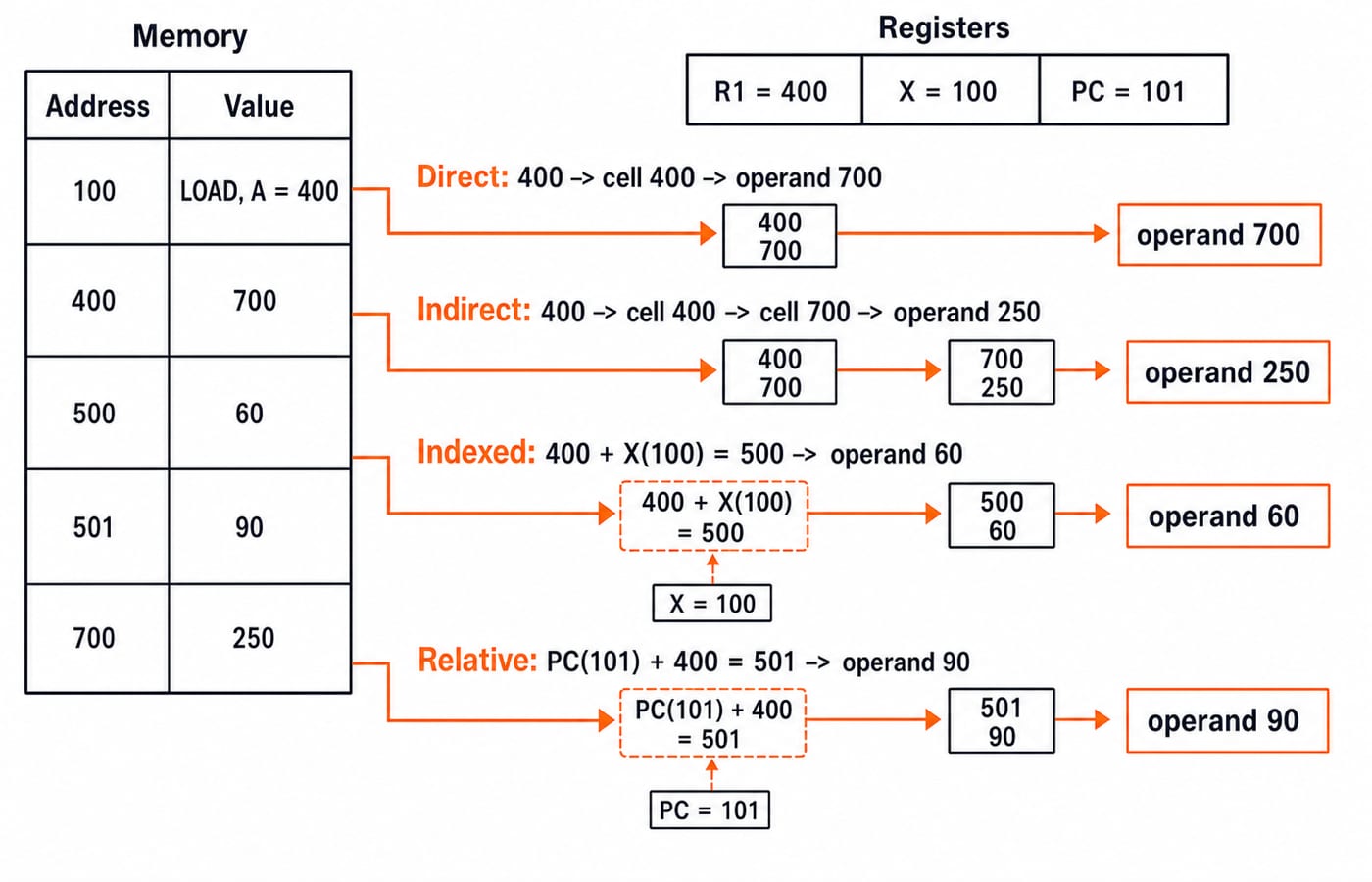
A one-word LOAD at address 100 has operand field A = 400, so the PC is 101 during execution. Registers hold R1 = 400 and X = 100. Memory has M[400] = 700, M[700] = 250, M[500] = 60, and M[501] = 90.
Now apply each rule carefully:
Immediate: operand =
400. No operand memory access is needed.Direct: EA =
400; operand =M[400] = 700. One access.Indirect: EA =
M[400] = 700; operand =M[700] = 250. Two accesses.Register indirect through R1: EA =
R1 = 400; operand =M[400] = 700. One access.Indexed: EA =
A + X = 400 + 100 = 500; operand =M[500] = 60. One access.Relative: EA =
PC + A = 101 + 400 = 501; operand =M[501] = 90. One access.
Two pairs repay a second look. Indirect and register indirect both start from the number 400 and still diverge: indirect reads M[400] to discover EA 700 and then reads the operand 250, while register indirect already holds EA 400 in R1 and reads the operand 700 in a single access. Direct and register indirect land on the same operand, 700, by different routes, which is why these six modes produce only five distinct operand values. Relative addressing uses PC 101, not the instruction address 100.
Common traps in instruction-format and addressing-mode questions
Relative addressing uses the incremented PC. Here that is 101. For a multi-word instruction, the increment follows the instruction length given in the question.
Do not count the instruction fetch when asked only for operand accesses. Immediate and register modes need zero operand memory accesses, register indirect needs one, and memory indirect needs two. Also remember the ordering rule: decrement before use, increment after use.
In a two-address instruction, one source is overwritten, which caused the extra MOV instructions in example A. In expanding-opcode problems, do not use all 16 short opcodes and then claim expanded opcodes too. The 2 escape patterns were left unused precisely to identify the expanded format.
How GATE and interviews test this topic
Computer Organization and Architecture is a core section of the GATE CS syllabus, and instruction formats and addressing modes sit in its instruction-set half. The topic almost always arrives as a short calculation: count the instructions an expression needs, count the opcode patterns a format still leaves free, or trace one effective address through to its operand.
Interviews use the same ideas to discuss instruction-set choices. Fixed, regular register formats simplify decoding and help explain pipelining in computer architecture. Variable-length formats can encode richer memory operands but are harder to decode. Operand-access counts feed straight into cache and memory-hierarchy numericals, since every extra reference travels through the memory system.
The short version, and the next step
Address count trades compact instructions against program length: 3, 6, 7, and 8 instructions in example A.
Expanding opcodes conserve encodings:
2 * 2^6 = 128one-address instructions here.An addressing mode is an EA rule plus an operand-access count.
Relative addressing uses the already incremented PC.
Memory indirect means two memory hops after instruction fetch.
Build this topic inside the wider syllabus with GATE Guidance by Sanchit Sir, then practise the numeric patterns under time pressure with the GATE Test Series. The GATE CS exam preparation hub places Computer Organization alongside the rest of the paper.
Keep learning
Programmed I/O: Polling, CPU Utilisation, Worked Examples and GATE Question Patterns
Follow one programmed-input transfer from control write to data read, then calculate how many polls one word costs and what a longer poll period buys.
Updated 7 Oct 20266 min readComputer Organization & Architecture
Multiprocessor Fundamentals: Architecture, Speedup and Worked Examples
Build a clear model of multiprocessor systems, then use it to calculate speedup and efficiency, trace a coherent write, and diagnose a lost update.
Updated 2 Oct 20265 min readComputer Organization & Architecture
Multiprocessor Classification: Flynn Taxonomy, Memory Models and Exam-Style Worked Examples
Learn how to choose the right multiprocessor classification axis, then solve a four-lane SIMD trace and a NUMA average-access-time problem step by step.
Updated 27 Sep 20266 min readComputer Organization & Architecture
Interrupt-Driven I/O Explained: CPU Handshake, Worked Timing Example and GATE Traps
Trace an interrupt from device request to return-from-interrupt, then compare polling, per-event interrupts, and DMA through worked timing examples.
Updated 25 Sep 20267 min readComputer Organization & Architecture