Computer Instruction Explained: Format, Instruction Cycle and a 16-Bit Worked Example
Decode an illustrative 16-bit load instruction, calculate its effective address, trace fetch through write-back, and learn the errors that change answers.
KnowledgeGate Team
Exam prep & CS education
Updated 25 Aug 20265 min read
Many students can identify an opcode in isolation but lose the question when instruction encoding, address calculation, PC movement and execution are combined. A single instruction can be traced from its 16-bit word to the final value written into a register by checking each field and state change in order. Each result depends on the stated ISA: field widths, address units, PC increments and side effects can differ between architectures.
Computer instruction meaning: the ISA contract
A computer instruction is an encoded command. Its fields tell the processor which operation to perform and where the operands come from or go.
The instruction set architecture, or ISA, defines this programmer-visible contract. It includes opcodes, registers, data types, addressing rules and instruction formats. The microarchitecture is different: it is the internal design that implements the ISA, perhaps with a particular pipeline, cache arrangement or control unit.
Our toy machine has fixed-length 16-bit instructions and word-addressed memory. It has eight registers, R0 to R7. Its program counter, PC, advances by one word after a normal fetch, and signed displacements use two's complement. Keep these rules visible while solving. The broader GATE CS Exam hub can help you place this concept within subject preparation.
Computer instruction types: operation, data and control
Instructions can move data, transform it or change control flow. Mnemonic syntax and side effects are ISA-specific, so LD, ADD, AND and BEQ must be interpreted under this toy ISA.
Class | Illustrative instruction | What changes |
|---|---|---|
Data transfer |
| Loads one memory word into |
Arithmetic |
| With |
Logical |
| With |
Control transfer |
| May replace the sequential |
An instruction usually combines an operation with zero or more explicit operands. Other inputs can be implicit, such as the PC or a condition-code register. Do not assume that every instruction reads memory or writes a general-purpose register.
Computer instruction format: decode the 16-bit word
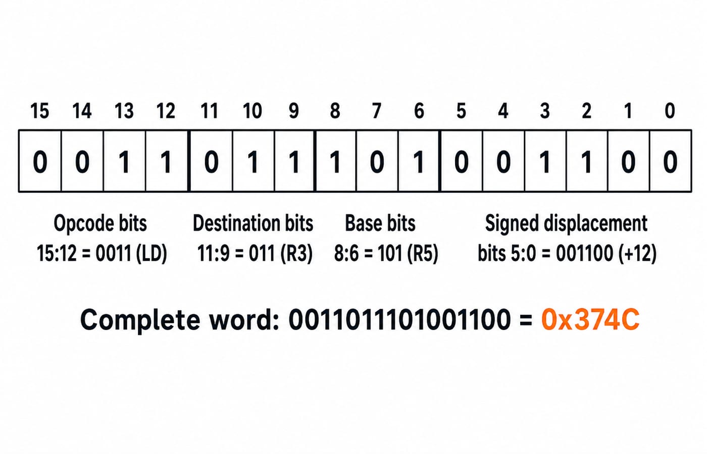
For LD R3, 12(R5), bits 15 down to 0 are divided as follows: opcode[15:12] has 4 bits, destination[11:9] has 3 bits, base[8:6] has 3 bits, and signed displacement[5:0] has 6 bits.
The capacities follow directly from the widths. Four opcode bits provide 2^4 = 16 bit patterns. Each 3-bit register field selects one of 2^3 = 8 registers. A 6-bit signed two's-complement displacement ranges from -2^5 = -32 to 2^5 - 1 = +31.
Now encode LD R3, 12(R5):
LD = 0011.R3 = 011andR5 = 101.+12 = 001100in 6 bits.Concatenation gives
0011 011 101 001100.Regrouping into 4-bit nibbles gives
0011 0111 0100 1100.Those nibbles are hexadecimal
3,7,4,C, so the stored word is0x374C.
Computer instruction cycle: trace fetch to write-back
Set the complete starting state first. PC = 200, M[200] = 0x374C, R5 = 1000, M[1012] = 37, and the old value of R3 = 9. Unless an address has a 0x prefix, memory addresses here are decimal word addresses.
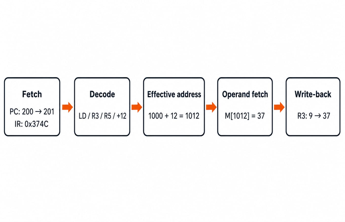
The state changes in this order:
Fetch:
IR <- M[200] = 0x374C, thenPC <- 201because a normal fetch advances one word.Decode: the control unit extracts
LD, destinationR3, baseR5and displacement+12.Effective address:
EA = R5 + 12 = 1000 + 12 = 1012.Operand fetch: the processor reads
M[1012] = 37.Execute and write-back:
R3 <- 37.
The final architectural state is PC = 201, R3 = 37 and R5 = 1000. The base register has not changed. A fault or a control-transfer instruction could alter this normal path, but neither occurs in this trace.
Computer instruction addressing: positive and negative displacement checks
The same 6-bit field can hold a negative displacement. The positive encoding is +12 = 001100. For -5, calculate 2^6 - 5 = 64 - 5 = 59. The 6-bit representation of 59 is 111011, so -5 is 111011 in 6-bit two's complement. Sign extension preserves the negative value, and R5 = 1000 gives EA = 1000 - 5 = 995.
If you read 111011 as unsigned 59, you will incorrectly calculate 1000 + 59 = 1059. The field width and signedness are part of the instruction format, not optional details.
Register addressing names a register. Immediate addressing carries a value in the instruction. Direct addressing carries an address, indirect addressing points to a location that holds an address, and base-plus-displacement addressing adds an encoded offset to a base register. Practise selecting and calculating these in Addressing modes and instruction formats in computer architecture explained.
Computer instruction mistakes that change the answer
Use this checklist before committing to a numerical answer.
Mistake | Wrong result | Correction |
|---|---|---|
Counting this word-addressed |
| One normal fetch advances one word, so it becomes |
Forgetting sign extension |
| As a signed 6-bit value, it is |
Returning the effective address | The answer is reported as |
|
Assuming | Unstated flag changes are added | Apply only the side effects defined by the toy ISA |
Instruction length must also be interpreted under the stated addressing convention. On a different byte-addressed ISA, a fixed 4-byte instruction at address 0x0040 makes the sequential PC become 0x0044, not 0x0041.
Computer instruction exam patterns: what to calculate under pressure
Most instruction questions reduce to a small set of calculations:
Allocate field widths and count available encodings.
Decode a binary or hexadecimal instruction.
Sign-extend an offset and calculate an effective address.
Trace
PC,IR, registers and memory through the micro-operations.Distinguish an address from the operand stored at that address.
Connect instruction dependencies to pipeline hazards and performance.
For a short performance check, suppose a workload executes 800,000 instructions at an average CPI = 1.25. It needs 800,000 x 1.25 = 1,000,000 cycles. At 1 GHz, the execution time is 1,000,000 / 1,000,000,000 s = 0.001 s = 1 ms. CPI here is an average for the stated workload, not a property of one opcode.
After practising dependencies and timing, use Pipelining in Computer Architecture: the 5-stage pipeline, speedup, and hazards to connect them to stalls and forwarding. The GATE Test Series provides mixed practice across instruction formats, addressing and performance.
Computer instruction short version and next step
Identify every field and its width.
Decode signed values using the stated representation.
State whether memory is word-addressed or byte-addressed.
Trace the
PCand data path in order.Report the final architectural state, not an intermediate address.
In the main example, 0x374C at PC 200 leaves PC = 201 and changes R3 from 9 to 37. If you want a structured path across GATE CS subjects, continue with GATE Guidance by Sanchit Sir.
Keep learning
Pipelining Basics in Computer Architecture: Clock Cycle, Speedup and Hazard Worked Examples
Learn how to calculate a pipeline clock, fill and drain time, finite-batch speedup, latency, throughput, and the cost of a load-use stall.
Updated 23 Oct 20266 min readComputer Organization & Architecture
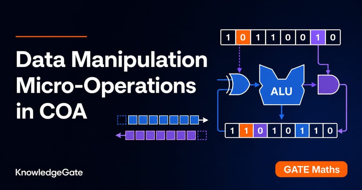
Data Manipulation Micro-Operations in COA: Arithmetic, Logic and Shift Operations Worked Step by Step
Learn a fixed-width method for tracing arithmetic, logic, and shift micro-operations. Every example tracks register values, result bits, carry, and overflow.
Updated 19 Oct 20265 min readComputer Organization & Architecture
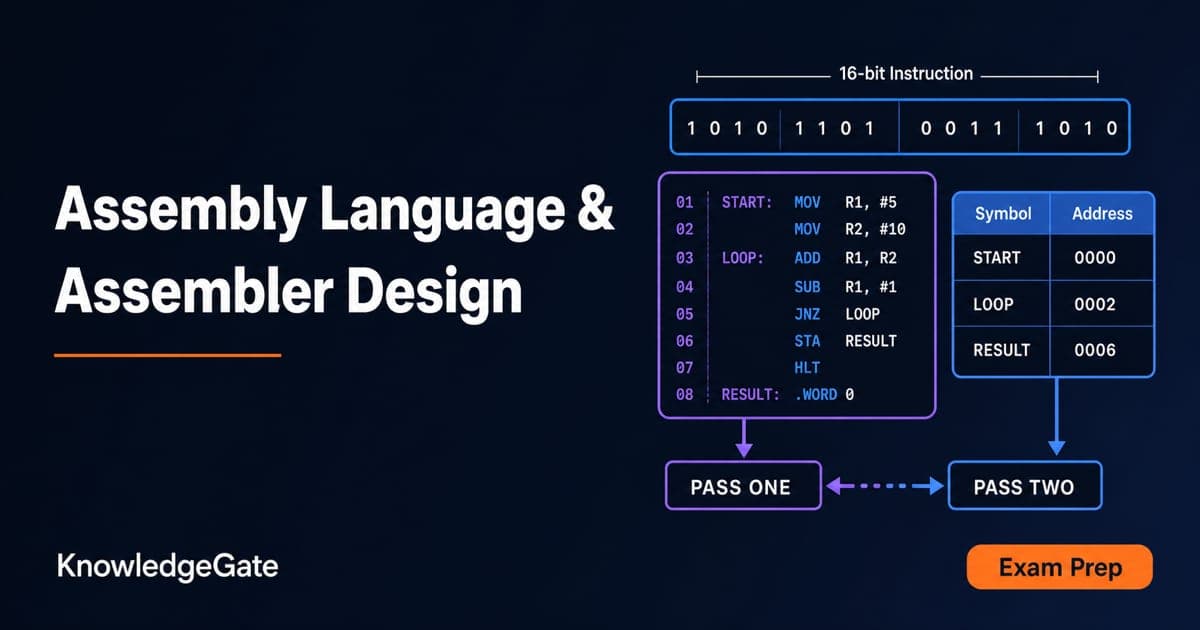
Assembly Language and Assembler Design: Two-Pass Translation with a Complete Worked Example
Follow a 16-bit Basic Computer program through pass one, pass two, hexadecimal encoding and execution, with every symbol, address and result shown.
Updated 15 Oct 20266 min readComputer Organization & Architecture
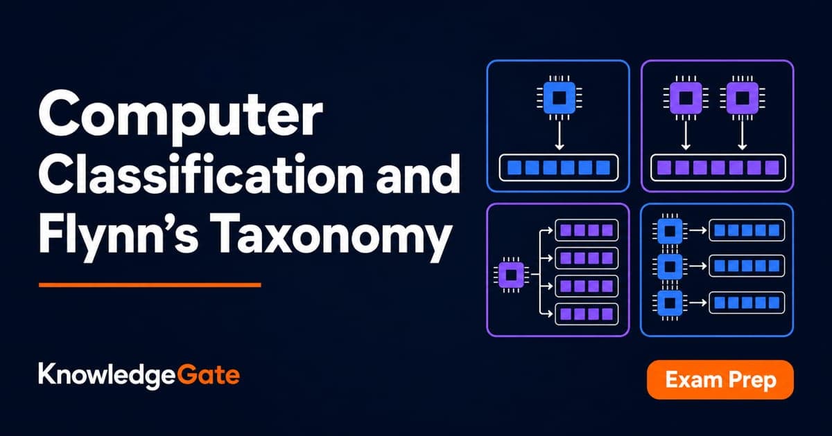
Computer Classification and Flynn’s Taxonomy: The Four Classes with a Worked Vector Example
A machine can belong to several computer classes at once. Learn the four classification axes, Flynn’s matrix, vector and multicore traces, and exam traps.
Updated 11 Oct 20266 min readComputer Organization & Architecture