Instruction Structure in Computer Organization: Fields, Encoding and Exam Problems
Learn how opcode, register, mode and displacement fields divide an instruction word. Follow checked examples for address forms, decoding and expanding opcodes.
KnowledgeGate Team
Exam prep & CS education
Updated 22 Sep 20265 min read
An instruction word looks like an arbitrary row of bits until every field is tied to a CPU decision. That is why learners may remember a format but still get stuck when the widths change. Read field boundaries, calculate encoding capacity and check an answer without memorising one architecture. The same habit carries across other GATE Computer Organization topics.
Start with the job of an instruction structure
An instruction is an encoded command that tells a processor what to do and where its operands are. An instruction set is the processor's collection of commands and conventions. An instruction format is the bit layout of one instruction.
Four field roles are especially useful:
The opcode identifies an operation such as add or load.
An operand or register specifier identifies a source or destination.
An addressing-mode field says how to interpret an operand.
An immediate or displacement field carries a constant or offset.
A real architecture may combine, omit or reinterpret fields. Fixed-length instructions make boundaries predictable and every bit countable. Variable-length instructions spend extra bits only when needed.
Start every such problem with two checks. All field widths must add to the full instruction width. A field of k bits can represent at most 2^k distinct bit patterns.
Address count changes which operands are explicit
Address count describes how many operand locations an instruction names. It does not determine the total word width, because opcode and operand fields still share the machine's bit budget.
Form | Typical notation | Implicit state | Encoding consequence |
|---|---|---|---|
Three-address | ADD R1, A, B | None in the data operation | Three explicit operand fields |
Two-address | ADD R1, B | R1 is also the destination | Two operand fields; one source is overwritten |
One-address | ADD B | The accumulator is source and destination | One explicit operand field |
Zero-address | ADD | The top two stack items are operands | No operand field in the arithmetic instruction |
The earlier Instruction Formats and Addressing Modes in COA: Complete Guide with Worked Examples owns the full one-expression translation and six-mode effective-address survey. This post uses only a compact address-form table before concentrating on bit-by-bit 16-bit decoding and a complete opcode-space conservation proof.
Decode a 16-bit instruction field by field
Consider this fixed toy format:
Bits | Width | Field |
|---|---|---|
| 4 | Opcode |
| 2 | Mode |
| 3 | Register |
| 7 | Unsigned displacement |
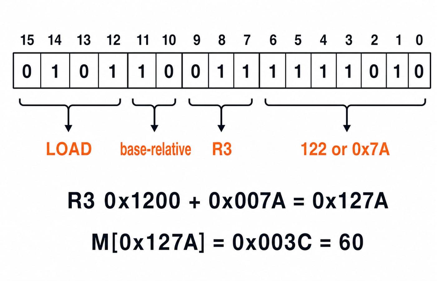
The widths total 4 + 2 + 3 + 7 = 16. Their capacities are 2^4 = 16 opcodes, 2^2 = 4 modes, 2^3 = 8 registers and 2^7 = 128 displacements. Because the displacement is unsigned, its values run from 0 through 127.
Now decode 0101 10 011 1111010:
0101meansLOADin this toy ISA.Mode
10means base-relative addressing.011selectsR3.1111010is64 + 32 + 16 + 8 + 2 = 122, which is0x7A.
Given R3 = 0x1200, the effective address is:
0x1200 + 0x007A = 0x127A
If M[0x127A] = 0x003C, the instruction loads 0x003C, which is decimal 60. The opcode table and mode meanings belong only to this example. Computer Instruction Explained: Format, Instruction Cycle and a 16-Bit Worked Example continues from field decoding through PC movement and write-back; this example stops at the bit boundaries and effective address. For binary-to-hex conversion, review Number Systems and Base Conversions.
Solve an expanding-opcode allocation problem
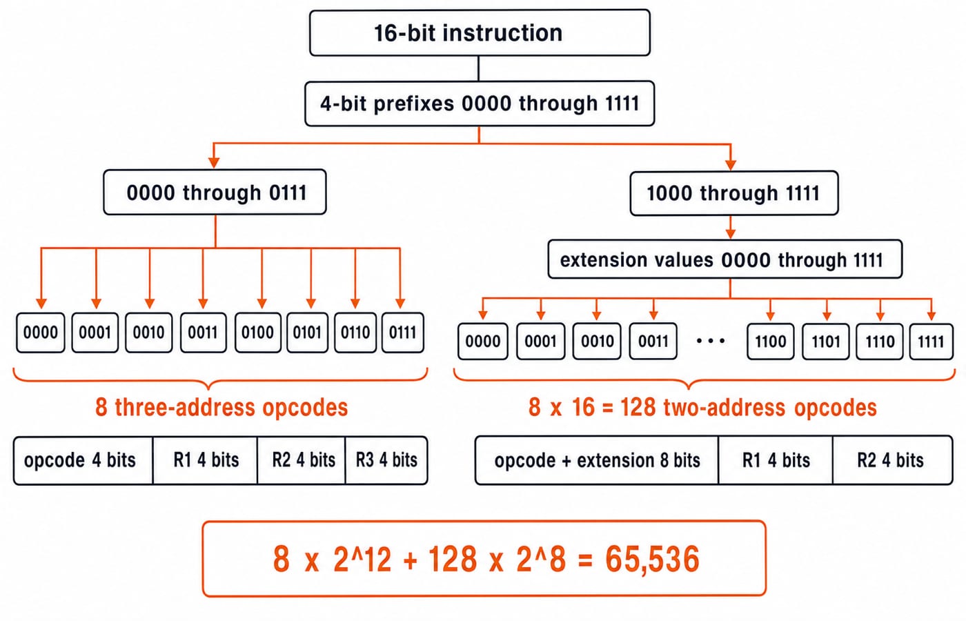
A 16-bit three-address instruction has three 4-bit register fields. They occupy 3 x 4 = 12 bits, leaving 16 - 12 = 4 opcode bits and 16 top-level prefixes.
Reserve prefixes 0000 through 0111 for 8 three-address operations. That leaves prefixes 1000 through 1111, also 8 prefixes, for another format.
A two-address format needs two 4-bit register fields. Removing the third field frees 4 extension bits. Each unused prefix expands into 2^4 = 16 opcodes. The maximum is:
8 x 2^4 = 8 x 16 = 128
The tempting answer 2^8 = 256 wrongly treats all 16 top-level prefixes as available. Half were already assigned.
Count complete 16-bit patterns to verify the allocation:
Three-address patterns:
8 x 2^12 = 8 x 4,096 = 32,768.Two-address patterns:
128 x 2^8 = 128 x 256 = 32,768.Total:
32,768 + 32,768 = 65,536 = 2^16.
Recognise the main exam-style question patterns
Instruction-structure problems usually belong to five families:
Calculate field widths from required counts.
Calculate available counts from given widths.
Decode a given bit string.
Allocate expanding opcodes among formats.
Translate an expression into zero-, one-, two- or three-address instructions.
Use the same solving order each time. Draw the word, write known widths, convert each required count N into ceil(log2 N) bits, subtract from the total, then interpret the remainder. A 12-bit address field has 2^12 = 4,096 patterns, representing addresses 0 through 4,095. Only then apply any stated addressing rule.
Begin with direct field-width questions before mixing decoding, signed values and opcode allocation.
Avoid traps that make correct arithmetic look wrong
Separate the number of values from the largest unsigned value. Seven bits provide 128 patterns, but the largest unsigned value is 127. Fifty registers require ceil(log2 50) = 6 bits because 2^5 = 32 is too small and 2^6 = 64 is sufficient.
Do not assume a signed displacement, byte addressing, alignment or opcode meaning unless the question provides it. In the earlier example, the 7-bit displacement was explicitly unsigned. If 1111010 were signed 7-bit two's complement, its value would be 122 - 128 = -6, and the effective address would be 0x1200 - 0x0006 = 0x11FA, not 0x127A.
Finish with a three-part self-check:
Do the field widths total 16?
Does each chosen value fit its field?
Does replaying the dataflow produce the requested result?
The short version, then practise in the right order
Fields divide an instruction word into CPU decisions, and their widths limit the encodings. Address-count forms change where operands live. Expanding opcodes reuse prefixes available from another format.
Practise in increasing order: direct width calculations, bit-string decoding, address-form comparison and finally expanding opcodes. GATE-focused learners can continue with GATE Guidance by Sanchit Sir. Work from the boundaries first, and the bit string stops looking arbitrary.
Keep learning

Multiprocessor Classification: Flynn Taxonomy, Memory Models and Exam-Style Worked Examples
Learn how to choose the right multiprocessor classification axis, then solve a four-lane SIMD trace and a NUMA average-access-time problem step by step.
Updated 27 Sep 20266 min readComputer Organization & Architecture

Interrupt-Driven I/O Explained: CPU Handshake, Worked Timing Example and GATE Traps
Trace an interrupt from device request to return-from-interrupt, then compare polling, per-event interrupts, and DMA through worked timing examples.
Updated 25 Sep 20267 min readComputer Organization & Architecture
Interface Addressing Explained: Memory-Mapped vs Isolated I/O with Worked Examples
Understand what an interface address selects, how memory-mapped and isolated I/O differ, and why partial decoding creates multiple addresses for the same register.
Updated 23 Sep 20266 min readComputer Organization & Architecture

Disk Structure and Disk Addressing for GATE: CHS, LBA and Worked Examples
Use one consistent disk geometry to connect platters, surfaces, tracks and sectors with capacity, CHS-to-LBA conversion, address width and access time.
Updated 21 Sep 20265 min readComputer Organization & Architecture