Control Unit Design in COA: Hardwired vs Microprogrammed, with Worked Examples
Build control unit design from timed micro-operations. Work through a fetch and LOAD sequence, derive control signals, and size horizontal and vertical microcode.
KnowledgeGate Team
Exam prep & CS education
Updated 4 Aug 20266 min read
Most students can recite that hardwired control is fast and microprogrammed control is flexible. The trouble begins with a fetch sequence, a Boolean control-signal expression, or a control-memory size. All three are built the same way, from the micro-operation up: name the register transfer that belongs to each clock step, read the signals that transfer needs off the timing table, then multiply words by bits.
What a control unit actually does
The control unit generates timed signals that drive the CPU datapath. It times register loads, bus gates, memory access, and ALU operations. It does not compute; it conducts.
It sequences fetch, decode, and execute. Each phase is split into micro-operations, single register-transfer steps completed in one clock. One machine instruction becomes a short, ordered list of them.
Two implementation styles produce these signals. A hardwired unit uses fixed logic; a microprogrammed unit stores control words in a small memory. Examinable ideas hang from this fork.
The instruction cycle as micro-operations
Register-transfer notation, or RTL, states what moves per clock. MAR <- PC copies the program counter into the memory address register. A sequence counter produces T0, T1, T2, and so on.
Consider a small single-bus CPU with PC, MAR, MBR, IR, AC, and one ALU. Its fetch sequence is:
Step | Register transfer | Control signals asserted |
|---|---|---|
T0 |
|
|
T1 |
|
|
T2 |
|
|
After T2, LOAD X, meaning AC <- M[X], continues:
Step | Register transfer | Control signals asserted |
|---|---|---|
T3 |
|
|
T4 |
|
|
T5 |
|
|
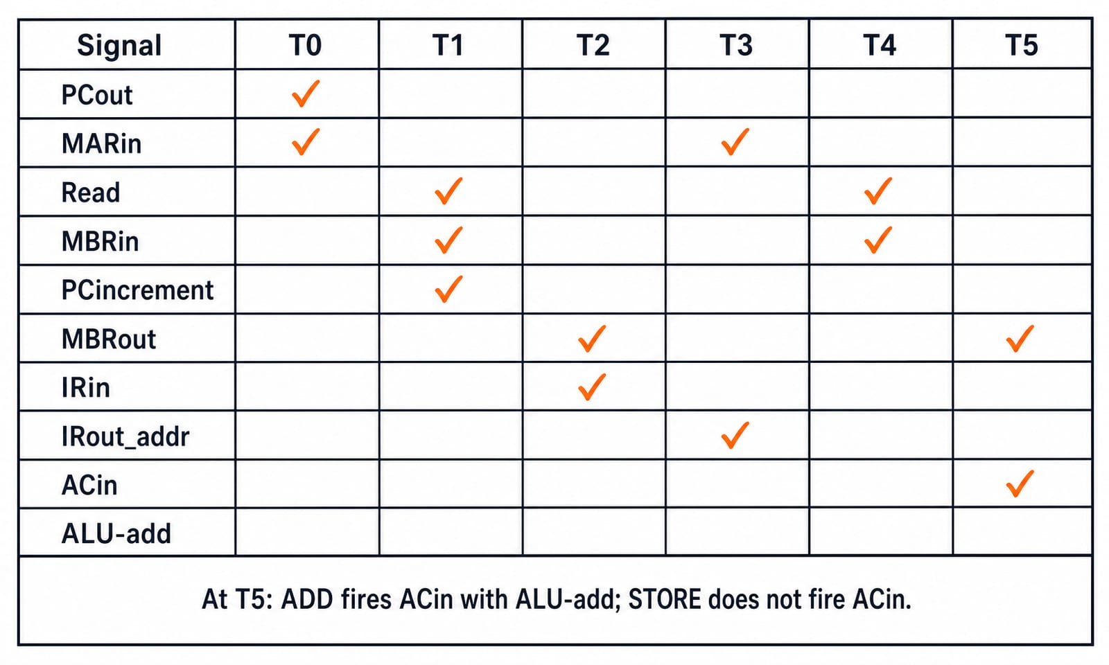
ADD X shares T3 and T4, then performs AC <- AC + MBR at T5 with MBRout, ALU-add, and ACin. STORE X shares T3, then performs MBR <- AC (ACout, MBRin) at T4 and M[MAR] <- MBR (Write) at T5. ACin therefore fires for LOAD and ADD, never STORE.
Hardwired control: signals as Boolean functions
In a hardwired unit, each signal is a Boolean function of timing, decoded opcode lines, and condition flags. The table says when each output must be 1.
Read three expressions from it:
MARin = T0 + T3 · (LOAD + STORE + ADD): fetch for every instruction, thenT3for the memory-reference instructions shown.ACin = T5 · (LOAD + ADD): only those instructions loadAC.Read = T1 + T4 · (LOAD + ADD): instruction fetch, then operand fetch forLOADorADD.
Here + is OR and · is AND. These are sums of products, one product for each relevant ticked cell.
A counter and decoder generate T0 to Tn; Sequential Circuits: Flip-Flops, Latches and Counters explains how that count is built. Each expression above then becomes one AND-OR network of the kind covered in Combinational Circuits: Multiplexers, Decoders and Adders. Expanded, Read = T1 + T4 · LOAD + T4 · ADD, so that one signal costs two AND gates plus an OR gate that also takes the T1 line directly. Logic is fast, but changing the instruction set means redesigning those gates. Small, regular instruction sets typically favour hardwired control.
Microprogrammed control: signals stored as words
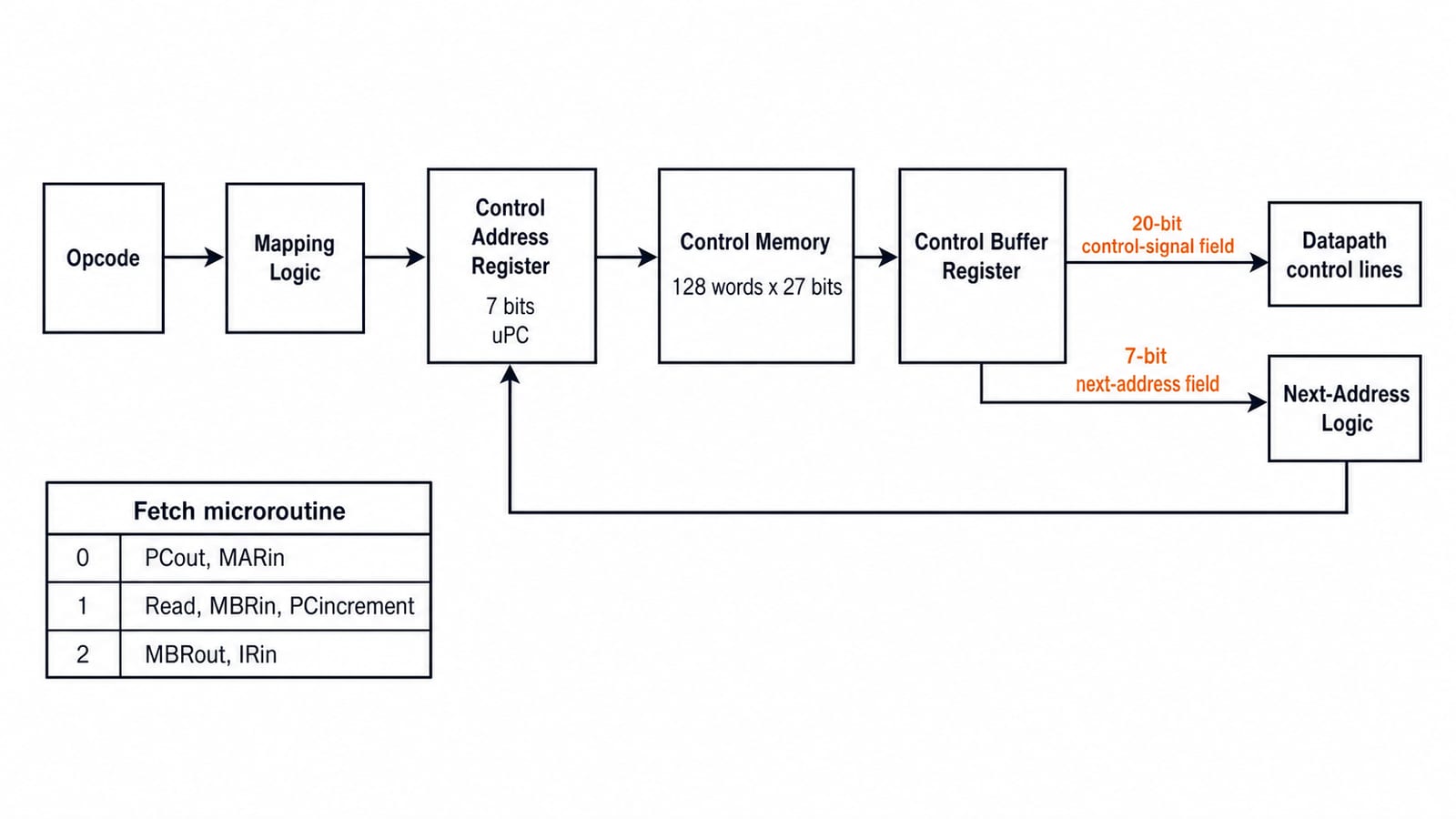
A microprogrammed unit stores signals as control words in a small, fast control store. A machine instruction runs a short microroutine of these words.
A word has control-signal and next-address fields. The control address register, or uPC, selects it for the control buffer register. One field drives the datapath; the other selects the next word. Mapping logic turns an opcode into a microroutine's start address.
The fetch sequence occupies three rows:
Address | Label | Control signals | Next address |
|---|---|---|---|
0 | FETCH0 |
| 1 |
1 | FETCH1 |
| 2 |
2 | FETCH2 |
| Mapped from opcode |
Size a horizontal store with 20 control signals and 128 words.
One bit per signal gives a 20-bit control-signal field.
Since
2^7 = 128, selecting any of 128 next addresses needs 7 bits.Control-word width =
20 + 7 = 27 bits.Control-memory size =
128 x 27 bits. Split the product to check it:27 x 100 = 2700,27 x 20 = 540,27 x 8 = 216.Therefore the size is
2700 + 540 + 216 = 3456 bits.In bytes,
3456 / 8 = 432 bytes.
One memory read per step makes this slower than hardwired control. Easy editing means complex instruction sets have historically favoured it.
Horizontal vs vertical microinstructions
Horizontal microcode uses one bit per signal. Valid combinations fire in parallel without decoding, but the word is wide. Vertical microcode encodes mutually exclusive groups. Its word is narrower, but it needs decoders and selects at most one signal per group.
Suppose a CPU has 50 control signals:
Horizontal field width =
50 bits.For vertical encoding, use five mutually exclusive groups of ten. A no-operation code makes
10 + 1 = 11 statesper group.2^3 = 8 < 11 <= 16 = 2^4, soceil(log2 11) = 4 bitsper group.Vertical field width =
5 x 4 = 20 bits.
The field falls from 50 to 20 bits. Vertical control pays with five decoders and limited parallelism. Horizontal trades width for speed and freedom; vertical does the reverse for a smaller store. That 20-bit figure depends on the grouping: one fully encoded field covering all 50 signals plus a no-operation code needs only ceil(log2 51) = 6 bits, since 2^5 = 32 < 51 <= 64 = 2^6, but it can assert a single signal per microinstruction. Size whichever grouping the question states, never a remembered one.
Traps that cost marks
Reversing the trade-off: hardwired is fast and rigid; microprogrammed is slower and flexible.
Treating a tendency as a law: RISC is typically hardwired and CISC often microprogrammed, but regularity and complexity are the reasons.
Confusing memories: control store is internal CPU memory for microinstructions, not main memory for machine instructions.
Forgetting fields: add next-address, condition, and mapping bits before multiplying width by word count.
Mixing horizontal and vertical: horizontal is wide and parallel; vertical is narrow and encoded. Include the extra no-operation state when finding an encoded group's width.
How GATE and interviews test control unit design
GATE CS asks about RTL sequences, Boolean control-signal expressions, and control-memory sizing. The official GATE Computer Science and Information Technology syllabus lists data-path and control unit under Computer Organization and Architecture. A sizing question hands you a signal count and a word count and asks for total control-memory bits; a hardwired question hands you a timing table and asks for one signal's Boolean expression.
Interviews test the trade-offs, why regular instruction sets suit hardwired control, and how it drives a pipelined datapath. Pipelining in Computer Architecture carries that link into control hazards.
KnowledgeGate's published question bank has about 90 Control Unit Design questions, part of roughly 1,700 across Computer Organization and Architecture. Hardwired versus microprogrammed and RISC versus CISC are dense areas.
The short version and your next step
A control unit is a timed signal generator.
One machine instruction becomes an ordered micro-operation sequence.
Hardwired control uses Boolean functions of time, opcode, and flags. It is fast but rigid.
Microprogrammed control reads control words from a control store. It is flexible but adds a memory read.
Horizontal microcode is wide and parallel; vertical microcode is narrow and encoded.
For control unit design sequenced with the rest of Computer Organization at GATE depth, GATE Guidance by Sanchit Sir is the full course. Browse more on GATE CS Exam Preparation.
Before calling the topic done, hand-write the fetch sequence, derive a control signal, and size a control memory. Reading makes it familiar; solving makes it dependable.
Keep learning
Programmed I/O: Polling, CPU Utilisation, Worked Examples and GATE Question Patterns
Follow one programmed-input transfer from control write to data read, then calculate how many polls one word costs and what a longer poll period buys.
Updated 7 Oct 20266 min readComputer Organization & Architecture
Multiprocessor Fundamentals: Architecture, Speedup and Worked Examples
Build a clear model of multiprocessor systems, then use it to calculate speedup and efficiency, trace a coherent write, and diagnose a lost update.
Updated 2 Oct 20265 min readComputer Organization & Architecture

Multiprocessor Classification: Flynn Taxonomy, Memory Models and Exam-Style Worked Examples
Learn how to choose the right multiprocessor classification axis, then solve a four-lane SIMD trace and a NUMA average-access-time problem step by step.
Updated 27 Sep 20266 min readComputer Organization & Architecture
Interrupt-Driven I/O Explained: CPU Handshake, Worked Timing Example and GATE Traps
Trace an interrupt from device request to return-from-interrupt, then compare polling, per-event interrupts, and DMA through worked timing examples.
Updated 25 Sep 20267 min readComputer Organization & Architecture