Register Transfer and Microoperations in COA: RTL Notation, Bus Design, and Every Microoperation Type with Worked Examples
RTL becomes easy when you treat every statement as parallel hardware action at one clock edge. This guide works through buses, subtraction, bit masks, insertion, and signed shifts.
KnowledgeGate Team
Exam prep & CS education
Updated 2 Aug 20266 min read73 views
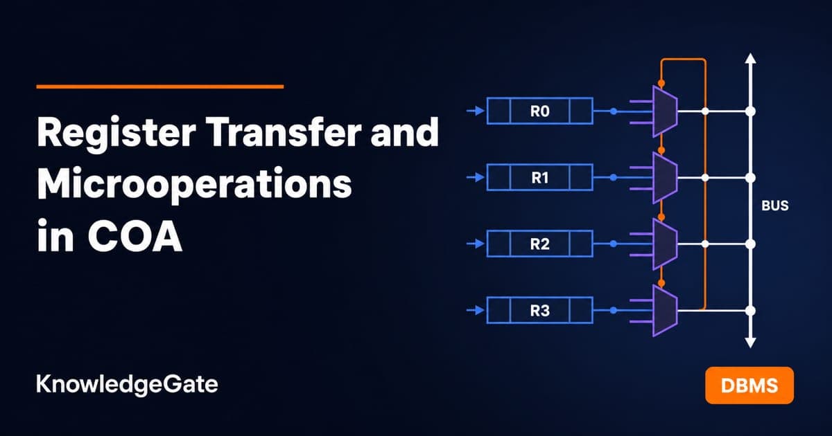
You can read R2 <- R1 aloud, yet a control function, shared bus and shift in one question still cause trouble. RTL looks like notation trivia, but exams and interviews test its semantics: what hardware does within one clock pulse. Four microoperation families (transfer, arithmetic, logic and shift), one bus-sizing rule and one signed-overflow test carry almost every question on the topic.
Register transfer language and its one-clock meaning
A register is a named group of flip-flops that stores a binary word. Common names include R1, PC, IR, AR and DR. Notation can select a range such as R1(7:0) or a byte half such as PC(H) and PC(L). A microoperation is one elementary operation performed on data in registers during one clock pulse.
R2 <- R1 means that R2 receives a copy of R1 at the next active clock edge. R1 keeps its value. With a control function, P: R2 <- R1 happens only at an edge where P is 1. This is parallel hardware behaviour, not a sequence of C assignments.
That distinction explains the exchange T: R1 <- R2, R2 <- R1. It needs no temporary register. Both right-hand sides are read from the old register values, then both new values are stored on the same edge. Registers are built from the edge-triggered elements covered in sequential circuits, flip-flops and counters.
Bus transfers: multiplexers and select lines
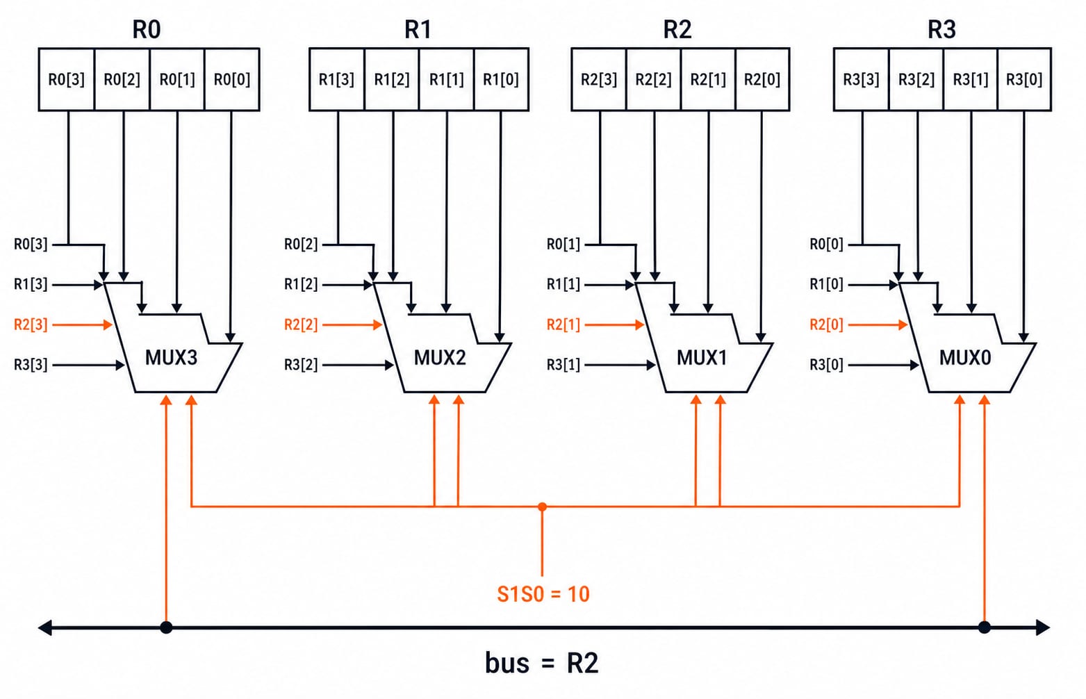
A common bus avoids building a separate path between every pair of registers. For four 4-bit registers R0 to R3, the bus needs four 4-to-1 multiplexers, one for each bit position. MUX i receives bit i from all four registers. The shared select lines S1 and S0 choose one source. When S1S0 = 10, every MUX selects its R2 input, so the complete bus carries R2.
The general rule is worth memorising:
k registers, each n bits wide, need n multiplexers.
Each multiplexer is k-to-1.
The source selection needs
ceil(log2 k)select lines.
Therefore, eight 16-bit registers need 16 multiplexers of 8-to-1, with three select lines. Do not count one MUX per register. Count one per bus bit.
Three-state buffers are an alternative. Each register contributes one buffer per bit, while a decoder activates only the selected register's enable line. Only one source may drive the bus at a time.
For memory, DR <- M[AR] reads the word addressed by AR into DR, while M[AR] <- DR writes DR there. AR supplies the address and DR carries the data.
Arithmetic microoperations with real bits
Basic arithmetic microoperations include addition R3 <- R1 + R2, subtraction R3 <- R1 + R2' + 1, increment, decrement and complement-based forms. Multiplication and division are not basic microoperations in this model. They are sequences of add and shift steps.
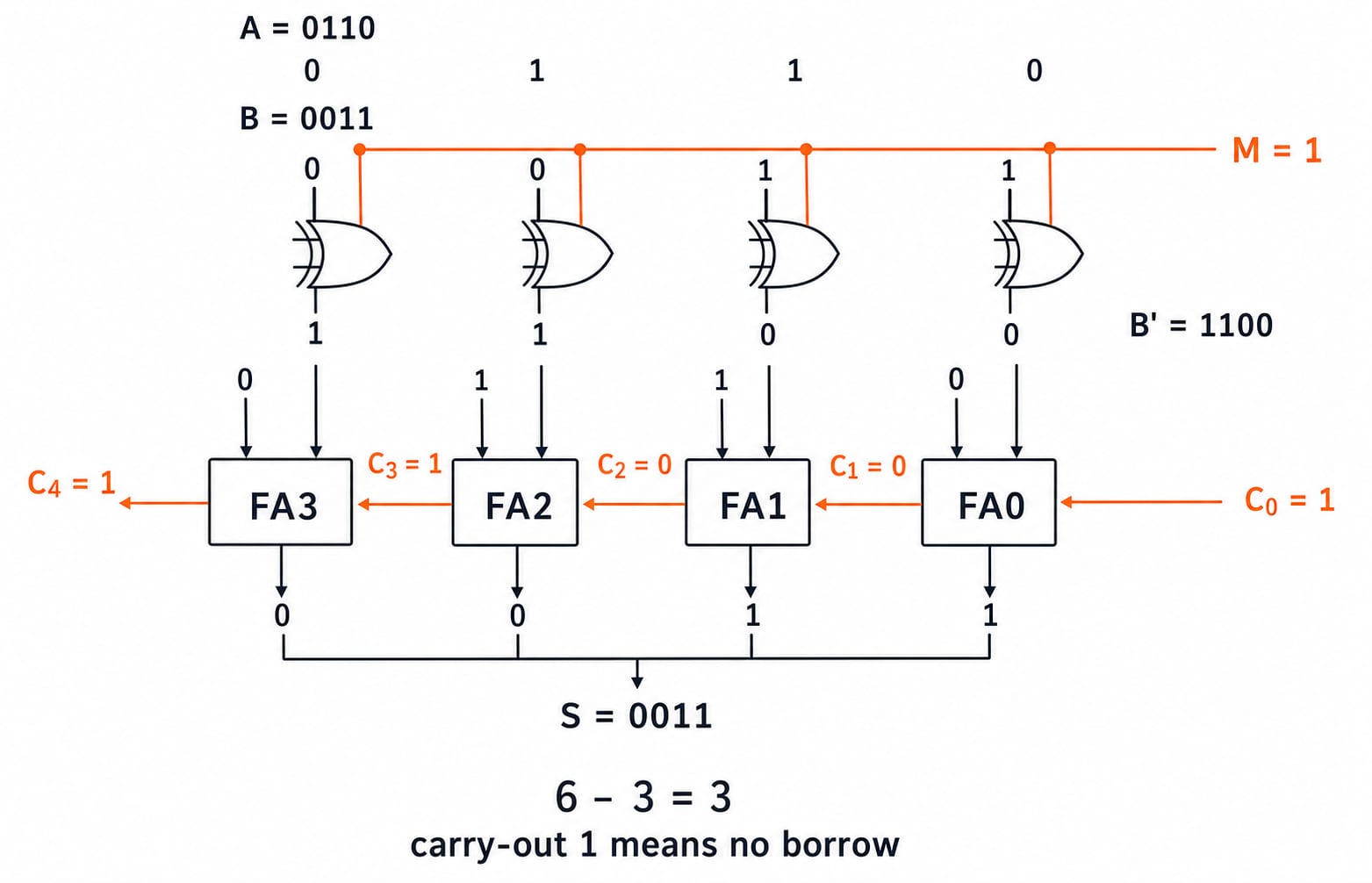
Now compute 6 - 3 in four bits:
R1 = 0110andR2 = 0011.Complement R2:
R2' = 1100.Add 1 to form its 2's complement:
1100 + 1 = 1101.Add:
0110 + 1101 = 1 0011.
The four sum bits are 0011, which is 3. Carry-out 1 means there was no borrow, so the positive result is already correct. For 3 - 6, carry-out would be 0 and the sum bits would hold the 2's complement representation of the negative result.
One 4-bit adder-subtractor can handle both operations. A mode bit M is XORed with every B input and also used as carry-in C0. With M = 0, B passes unchanged and C0 is 0. With M = 1, B becomes B' and C0 supplies the required 1. A binary incrementer can use half adders: 0111 + 1 = 1000.
Logic microoperations: set, clear, mask and insert
AND, OR, XOR and complement operate independently on corresponding bits. With A = 1010 and B = 1100, four common patterns are:
Operation | RTL form | Result | Meaning |
|---|---|---|---|
Selective set |
|
| Set positions where B is 1 |
Selective complement |
|
| Flip positions where B is 1 |
Selective clear |
|
| Clear positions where B is 1 |
Mask |
|
| Clear positions where B is 0 |
Insert is a two-step favourite. Start with A = 0110 1010 and insert 1001 into the left nibble. First clear that nibble: 0110 1010 AND 0000 1111 = 0000 1010. Then insert the new field: 0000 1010 OR 1001 0000 = 1001 1010. Firmware uses the same pattern to edit selected fields in flag bytes and device registers.
Shift microoperations and signed overflow
Take the 8-bit word R = 1001 1010. In 2's complement it represents -102.
Logical shift right gives
0100 1101, filling the MSB with 0.Circular shift left gives
0011 0101, wrapping the old MSB 1 into the LSB.Arithmetic shift right gives
1100 1101, replicating the sign bit. This is -51, so it divides -102 by 2 while preserving the sign.
Arithmetic shift left moves the bits in the same way as logical shift left: 1001 1010 becomes 0011 0100. Here the sign changes from 1 to 0, so overflow has occurred. Before shifting, test V = R(n-1) XOR R(n-2). The two leading bits are 1 and 0, hence V = 1 XOR 0 = 1. The flag is correct because doubling -102 gives -204, outside the signed 8-bit range from -128 to 127.
The key contrast is on right shifts. Arithmetic right replicates the sign bit; logical right inserts 0. On left shifts, the bit movement matches, but arithmetic shift left must report signed overflow.
How GATE and interviews test register transfer
The official GATE CS syllabus lists ALU, data-path and control unit under Computer Organization and Architecture. Register transfer sits underneath all three.
Questions usually take one of four shapes:
One-clock semantics, especially whether a parallel exchange needs a temporary register. It does not.
Bus hardware counting: k registers of n bits require n k-to-1 MUXes and
ceil(log2 k)select lines.2's complement subtraction, followed by the correct reading of carry-out.
Signed shifts, sign extension and arithmetic-left overflow.
In interviews, Verilog non-blocking assignments use old right-hand-side values before updating registers together, just like the exchange rule. A common follow-up asks what arithmetic right shift does to an odd negative value: 1001 1011 is -101, and shifting gives 1100 1101 = -51, which is floor(-101/2) rather than the -50 that C integer division returns. Pipeline stage registers scale this idea across a processor, as pipelining in computer architecture explains. Use the GATE CS category hub to place the topic in the wider subject line-up.
Traps that cost marks
Reading RTL like C: evaluate every right-hand side from old values, then commit all left-hand sides together.
Treating a control function as continuous transfer: P only qualifies an active clock edge. The transfer occurs once on each qualifying edge.
Using logical right shift on a signed value:
0100 1101is +77, not the sign-preserving -51 produced by arithmetic right shift.Counting a MUX per register: eight 16-bit registers need 16 MUXes, not eight.
Calling multiplication one basic microoperation: in this model, it is an add-shift sequence rather than one elementary register operation.
The short version and the next step
One clock pulse completes one microoperation. A bus for k registers of n bits uses n k-to-1 MUXes. Subtraction adds the 2's complement and reads carry-out. Logic operations set, complement, clear, mask and insert fields. Shifts are logical, circular or arithmetic, with signed overflow checked on arithmetic left shift.
Use GATE Guidance by Sanchit Sir when you are learning COA in sequence. Use the GATE Test Series when the concepts are settled and you need timed practice on these question shapes.
Keep learning
Programmed I/O: Polling, CPU Utilisation, Worked Examples and GATE Question Patterns
Follow one programmed-input transfer from control write to data read, then calculate how many polls one word costs and what a longer poll period buys.
Updated 7 Oct 20266 min readComputer Organization & Architecture

Multiprocessor Fundamentals: Architecture, Speedup and Worked Examples
Build a clear model of multiprocessor systems, then use it to calculate speedup and efficiency, trace a coherent write, and diagnose a lost update.
Updated 2 Oct 20265 min readComputer Organization & Architecture

Multiprocessor Classification: Flynn Taxonomy, Memory Models and Exam-Style Worked Examples
Learn how to choose the right multiprocessor classification axis, then solve a four-lane SIMD trace and a NUMA average-access-time problem step by step.
Updated 27 Sep 20266 min readComputer Organization & Architecture
Interrupt-Driven I/O Explained: CPU Handshake, Worked Timing Example and GATE Traps
Trace an interrupt from device request to return-from-interrupt, then compare polling, per-event interrupts, and DMA through worked timing examples.
Updated 25 Sep 20267 min readComputer Organization & Architecture