Combinational circuits: multiplexers, decoders and adders explained
A combinational circuit's output depends only on its current inputs, with no stored state. Multiplexers, decoders, encoders and adders are the blocks GATE keeps testing, and a single 4-to-1 MUX can implement any three-variable Boolean function using just one inverter.
KnowledgeGate Team
Exam prep & CS education
Updated 15 Jul 20265 min read
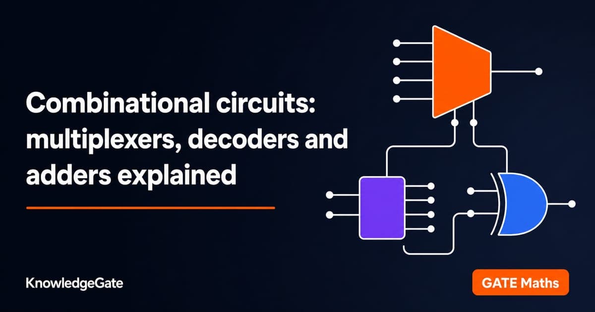
A combinational circuit has no memory. Its outputs depend only on the present inputs, computed by pure logic, with no feedback and no clock. That single property is what separates the multiplexer, the decoder, the encoder and the adder from the flip-flops and counters of sequential design. Master those four blocks and you can both analyse a given circuit and build one to match a specification, which is exactly what GATE asks.
Combinational versus sequential: the defining line
In a combinational circuit, if you know the inputs you know the outputs, full stop. There is no stored state, so the same input pattern always produces the same output. The moment a circuit feeds an output back to influence a future output, or latches a value across a clock edge, it becomes sequential. Adders, multiplexers and decoders are combinational; counters, shift registers and flip-flops are not, because each of them holds a value between clock edges. Keeping this boundary sharp stops a lot of confusion later.
Multiplexers: selecting one of many
A multiplexer (MUX) routes one of several data inputs to a single output, chosen by a set of select lines. A MUX with n select lines handles 2^n data inputs. A 4-to-1 MUX, for instance, has four data inputs I0 to I3, two select lines S1 and S0, and one output Y. The select value picks which input reaches the output: S1 S0 = 00 passes I0, 01 passes I1, 10 passes I2, 11 passes I3. Written as logic, Y = S1' S0' I0 + S1' S0 I1 + S1 S0' I2 + S1 S0 I3.
The demultiplexer is the mirror image: one input, one output selected out of 2^n by the select lines. Where a MUX is a data selector, a DEMUX is a data distributor.
Decoders and encoders
A decoder converts an n-bit binary code into one active line out of 2^n. A 2-to-4 decoder takes inputs A and B and asserts exactly one of four outputs, each output being one minterm: D0 = A' B', D1 = A' B, D2 = A B', D3 = A B. Because each output is a minterm, a decoder plus an OR gate can implement any Boolean function directly from its minterm list, which is where the sum-of-products form from Boolean algebra and K-map minimization pays off. Add an enable line and decoders cascade to build larger ones.
An encoder does the reverse, turning one active input out of 2^n into an n-bit code. The catch is ambiguity when two inputs are active at once, which is why the priority encoder exists: it resolves conflicts by outputting the code of the highest-priority active input and usually flags validity with an extra output. Encoders and priority encoders are a steady source of exam questions precisely because candidates forget the priority rule.
Half adders and full adders
Binary addition is built from two small circuits.
A half adder adds two single bits A and B, producing a sum and a carry. Sum = A XOR B, and Carry = A B. It cannot accept a carry coming in, which limits it to the least significant bit.
A full adder adds three bits, A, B and a carry-in Cin, producing Sum = A XOR B XOR Cin and Cout = A B + Cin (A XOR B). Chain n full adders, carry-out to carry-in, and you get an n-bit ripple-carry adder.
The ripple-carry adder is simple but slow, because each stage waits for the carry from the stage below, so the worst-case delay grows with the number of bits. That delay is the motivation for the carry-lookahead adder, which computes every carry straight from the input bits using generate (G = A B) and propagate (P = A XOR B) terms rather than waiting on the stage below. The exam often asks you to compare the two on propagation delay.
A MUX as universal logic: a worked example
Here is the result GATE loves. A 2^n-to-1 multiplexer can implement any Boolean function of n variables directly, and with one trick it can implement a function of n+1 variables. Connect the n higher variables to the select lines; then each data input must be set to whatever the function equals for that select combination, which is one of 0, 1, the remaining variable, or its complement.
Implement F(A, B, C) = sum of minterms m(1, 2, 6, 7) using a 4-to-1 MUX. Put A and B on the select lines S1 and S0, leaving C to drive the data inputs. Split the minterms by the AB value and see what F depends on within each:
A B (select) | Minterms in this column | F in terms of C |
|---|---|---|
0 0 | m0 (F=0), m1 (F=1) | F = C |
0 1 | m2 (F=1), m3 (F=0) | F = C' |
1 0 | m4 (F=0), m5 (F=0) | F = 0 |
1 1 | m6 (F=1), m7 (F=1) | F = 1 |
So wire the data inputs as I0 = C, I1 = C', I2 = 0, I3 = 1. That single 4-to-1 MUX now computes a three-variable function with no extra gates beyond one inverter for C.

Trace one row to trust it: for A B = 01, the MUX selects I1 = C', and the truth table says F is 1 when C is 0 and 0 when C is 1, which is exactly C'. The method always works because the select lines fix all but one variable, and a single-variable function can only be 0, 1, the variable, or its complement.
How combinational circuits are tested in GATE
Combinational Circuit is a heavily examined topic: the KnowledgeGate question bank carries over 260 questions on it, inside a Digital Electronics pool of more than 1,500. Expect a MUX-implementation question like the one above, a "realise this function using a decoder and OR gates" question, a priority-encoder truth-table question, and a full-adder propagation-delay comparison. A frequent twist gives you a MUX with one variable already on a data line and asks for the output expression, which is the worked method run in reverse.
The usual mistakes are mixing up MUX and DEMUX behaviour, forgetting that a decoder output is a minterm (so you OR the ones you need), and ignoring the priority rule on encoders. Each is a definitional slip, cured by building a few circuits by hand rather than reading about them.
The short version
Learn the four blocks by what they do to data: a MUX selects, a DEMUX distributes, a decoder expands a code to minterms, an encoder compresses. Then practise implementing functions with a MUX and with a decoder until it is automatic. Work the topic on the Combinational Circuit learn module and place it in the subject on the Digital Electronics learn hub. For the full GATE sequence, from Boolean algebra into combinational and then sequential design, GATE Guidance by Sanchit Sir orders it the way the syllabus builds, with the CS Fundamentals category collecting the rest.
Keep learning
Graphical Method in Linear Programming: Feasible Region, Corner Points and Optimality with a Worked Example
Learn the two-variable graphical method in the right order, then solve and audit a complete maximisation model without trusting the sketch alone.
Updated 21 Oct 20265 min readEngineering Mathematics

Duality in LP: Construct the Dual, Solve a Worked Example, and Apply Key Properties
Learn a reliable matrix-first method to form an LP dual, solve both programs to value 21, and use duality properties to check optimality and avoid sign errors.
Updated 17 Oct 20266 min readEngineering Mathematics

Commutative Property and Abelian Groups: Tests, Worked Examples and Exam Traps
Learn how to separate commutativity from the other group axioms, test custom operations step by step, and avoid the usual classification traps.
Updated 13 Oct 20266 min readEngineering Mathematics

Closure, Semigroup and Monoid: Worked Algebraic Structure Examples
Learn a reliable order for testing closure, associativity and identity. Worked tables and counterexamples show exactly when a structure becomes a semigroup or monoid.
Updated 9 Oct 20266 min readEngineering Mathematics