

Hardwired vs Microprogrammed Control Unit: Worked Examples and Exam Traps
See how hardwired logic and microcode produce the same CPU control signals. Trace ADD R1, R2 across six clocks, encode its control words, and solve a control-store sizing problem.
KnowledgeGate Team
Exam prep & CS education
Updated 7 Nov 20266 min read
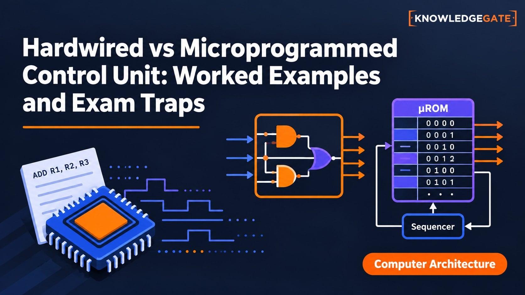
It is easy to memorise that hardwired control is faster and microprogrammed control is flexible. The trouble starts when a question asks you to turn an instruction into timing signals, a control word, or a control-store size. Hardwired and microprogrammed controllers execute ADD R1, R2 with different signal-generation methods, while control-store capacity depends on control bits, address bits, and sequencing bits. The same simplified datapath exposes both implementations without changing the datapath or operand values.
What the control unit actually controls
The datapath contains the PC, MAR, MDR, IR, registers, ALU, bus, and temporary registers. The control unit decides which values move, which ALU operation runs, when memory is accessed, and when an instruction ends. A signal such as PCout or R1in is a binary command, not bus data.
The controller maps the instruction, state, flags, and inputs to signals and a next state. A shared fetch precedes instruction-specific execution. Both controller types implement this mapping. The CS Fundamentals category covers surrounding concepts.
Hardwired control unit: decoder, timing, and logic
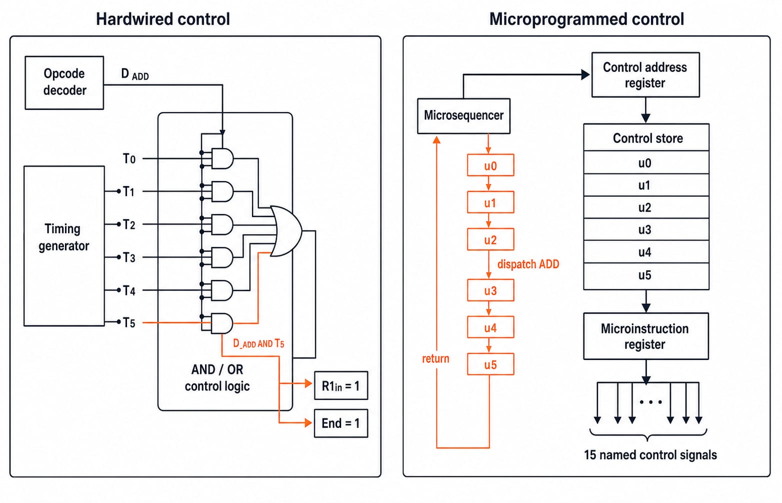
A hardwired controller uses an opcode decoder for one-hot lines such as D_ADD, a sequence counter for T0 through T5, and output gates. End resets the counter for the next fetch.
For our instruction, the common fetch equations are:
PCout = T0andMARin = T0Read = T1,MDRin = T1, andIncPC = T1MDRout = T2andIRin = T2
The ADD execute equations are R1out = D_ADD*T3, Ain = D_ADD*T3, R2out = D_ADD*T4, ADD = D_ADD*T4, Gin = D_ADD*T4, Gout = D_ADD*T5, R1in = D_ADD*T5, and End = D_ADD*T5.
Check one output. At D_ADD = 1 and T5 = 1, R1in = 1*1 = 1 and End = 1. At T4, R1in = 1*0 = 0. A changed sequence therefore requires changed decoder or gating logic, even if the datapath is unchanged.
Microprogrammed control unit: control store and sequencer
In a microprogrammed controller, a micro-PC selects a control-store word. A microinstruction register holds it and activates signals. A microsequencer selects the next address sequentially, by opcode, or by a condition. Control memory is not program memory.
A horizontal microinstruction can give every signal its own bit. A vertical format encodes choices into fields, reducing width but requiring decoding and possibly restricting combinations. This is a width-versus-decoding trade-off, not an absolute speed rule.
Here, u0 to u2 fetch the instruction. Dispatch after u2 enters ADD at u3; u3 to u5 execute it; u5 asserts End and returns to u0.
Worked instruction: trace ADD R1, R2 through six clocks
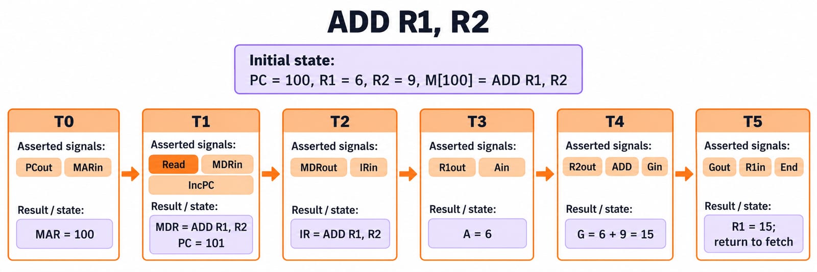
Assume a simplified single-bus datapath with PC = 100, R1 = 6, R2 = 9, and M[100] = ADD R1, R2. The instruction means R1 <- R1 + R2. The ALU uses temporary input register A and output register G. Memory supplies the addressed word during T1. Ignore cache misses, interrupts, and variable memory latency.
Clock | Asserted signals | Microoperation | Values after the edge |
|---|---|---|---|
|
|
|
|
|
|
|
|
|
|
|
|
|
|
|
|
|
|
|
|
|
|
|
|
The opcode selects ADD, while operand fields select R1 and R2. Addressing Modes and Instruction Formats explains how those operand fields are represented.
Encode the sequence as a horizontal microprogram
Fix this 15-bit order:
[PCout, MARin, Read, MDRin, IncPC, MDRout, IRin, R1out, Ain, R2out, ADD, Gin, Gout, R1in, End]
Address | Control word | Active signals |
|---|---|---|
|
|
|
|
|
|
|
|
|
|
|
|
|
|
|
|
|
|
In u4, bits 10 to 12 assert R2out, ADD, and Gin, so G = 15. In u5, bits 13 to 15 assert Gout, R1in, and End, so R1 = 15. A bit string needs its field order.
Hardwired logic derives each set from D_ADD and Tj; the microprogram reads it from storage. Both end with PC = 101, R1 = 15, and R2 = 9.
Hardwired vs microprogrammed control: comparison and traps
Point | Hardwired control | Microprogrammed control |
|---|---|---|
Implementation | Decoder, state or timing logic, and gates | Control store, micro-PC, register, and sequencer |
Control latency | Commonly avoids a control-store lookup | Includes microinstruction access and sequencing |
Design changes | Logic changes may be required | Sequences are easier to alter when the store permits updates |
Cost shape | More custom logic as complexity grows | Memory width and depth grow with the control format |
Best fit | Regular, latency-sensitive control | Complex instruction sequencing |
Control Unit Design in COA: Hardwired vs Microprogrammed owns the broader multi-instruction timing table and derives Boolean equations for MARin, ACin, and Read. The ADD trace here instead holds one instruction constant while matching its six clocks to an exact 15-bit horizontal microroutine.
Five traps matter. Microcode is not ISA machine code. One microinstruction is not a machine instruction. Microprogrammed controllers still contain hardware. Horizontal versus vertical describes encoding, not controller implementation. “RISC is always hardwired and CISC is always microprogrammed” is an unsafe shortcut.
D_ADD*T5 -> R1in exposes hardwired generation. Address u5 containing 000000000000111 exposes microprogrammed generation. Both produce R1 <- G = 15, then End = 1.
How exams test control-unit design
Exam questions commonly ask you to identify a controller, derive a signal, decode a horizontal word, compare formats, or calculate control-store size.
Hardwired vs Microprogrammed Control Unit for GATE owns horizontal-versus-vertical field sizing, condition-select fields, and two full store-capacity numericals. The calculation below is narrower: it checks every field after encoding one six-word ADD microroutine.
Suppose a control store has 512 words. Each word contains 15 control bits, a next-address field, and 2 sequencing bits.
Next-address width =
log2(512) = 9bits.Microinstruction width =
15 + 9 + 2 = 26bits.Total capacity =
512 * 26 = 13312bits.In bytes, capacity =
13312 / 8 = 1664bytes.
512 * 15 wrongly omits the next-address and sequencing fields. The control address register needs 9 bits, not 8, because 8 bits address only 256 words. Also, T0 to T5 are successive steps for one instruction, not overlapped stages. Pipelining in Computer Architecture covers that separate idea.
Hardwired and microprogrammed control units: short version
Use five steps: write the instruction semantics, list its microoperations, mark the signals, identify whether logic or storage produces them, then include every field in width calculations. The final values are PC: 100 -> 101, R1: 6 -> 15, u4 = 000000000111000, u5 = 000000000000111, and 1664 bytes.
Now repeat only the execute phase with R1 = 11 and R2 = 4. The words remain u3, u4, and u5; A = 11, G = 15, and final R1 = 15. The control signals describe actions, while register contents supply data.
For connected fundamentals, use Zero to Hero, the complete CS course after reproducing both traces yourself.
Keep learning

Hardwired and Microprogrammed Control Unit MCQs: 12 Solved Questions with Explanations
Work through 12 control-unit questions covering core definitions, speed order, register operations, microinstruction fields and control-word sizing.
Updated 20 Aug 20268 min read173 viewsComputer Organization MCQs

Control Unit Design in COA: Hardwired vs Microprogrammed, with Worked Examples
Build control unit design from timed micro-operations. Work through a fetch and LOAD sequence, derive control signals, and size horizontal and vertical microcode.
Updated 4 Aug 20266 min read56 viewsComputer Organization & Architecture

Hardwired vs Microprogrammed Control Unit for GATE: Microinstruction Sizing Numericals Solved
Separate the qualitative comparison from the sizing numerical. Two worked control-store examples show exactly where every microinstruction bit comes from.
Updated 30 Oct 20267 min read58 viewsComputer Organization & Architecture

Control Unit Design Cross-Concept MCQs: 12 Solved Questions with Explanations
Solve 12 published Control Unit Design questions covering address capacity, datapath scheduling, DRAM refresh, register widths, bitwise arithmetic and decoding. Each answer shows the decision or calculation that matters.
Updated 30 Oct 20267 min readComputer Organization MCQs