

Structural UML Diagrams MCQs and Practice Problems: 11 Solved Questions
Solve seven MCQs and four application problems on structural UML diagrams. Each fresh explanation shows how to identify the diagram from its abstraction level and relationships.
KnowledgeGate Team
Exam prep & CS education
Updated 7 Nov 20266 min read
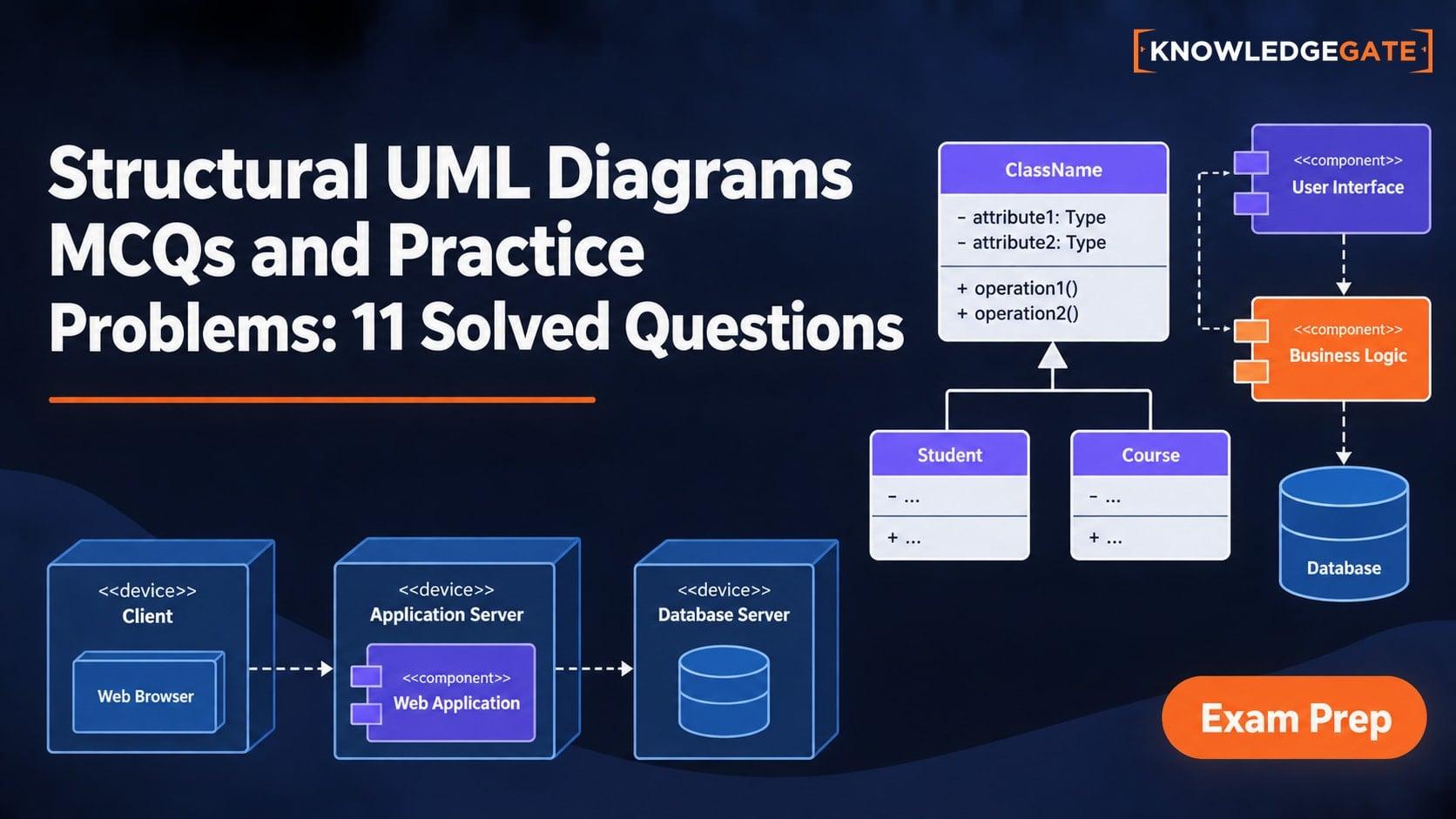
Class, object, package, component and deployment diagrams are structural UML diagrams. Seven MCQs and four application problems test the five families. Use “instances at one moment”, “logical grouping”, “deployable module” and “hardware node” to identify the required view. The UGC NET CS Exam Preparation collection provides topic-level practice beyond these 11 questions. The earlier Modelling and UML Fundamentals MCQs and Short Answers: 10 Solved Questions separates structural from behavioural views; these questions distinguish the five structural families.
Structural UML diagrams: the five-way distinction to use before solving
Diagram | What it represents |
|---|---|
Class | Types, attributes and static relationships |
Object | Named instances with attribute values at one instant |
Package | Logical grouping and namespaces |
Component | Replaceable modules, provided or required interfaces, and dependencies |
Deployment | Software artifacts placed on hardware or execution nodes |
A class diagram relates Customer(customerId, name) to Order(orderId, createdOn). An object diagram freezes one instant: customer17:Customer {name="Asha"} links to order42:Order {createdOn="2026-07-21"}.
Packages group booking.core, payments and notifications. Components express Booking Service requiring PaymentPort, while Payment Service provides it. Deployment maps the client, service and database to Client-12 <-> App-01 <-> DB-01. Identify the noun, relationship and abstraction level.
Structural UML MCQs 1-3: components and packages
Question 1
Which UML diagram represents system components and their dependencies?
A. Class diagram
B. Component diagram
C. Object diagram
D. Sequence diagram
Correct answer: B. Component diagram.
Components and dependencies identify a component diagram. Class and object diagrams show types or instances; sequence diagrams show behaviour over time.
Question 2
In UML, grouping related classes, interfaces, and components into logical containers is achieved through:
A. Package diagram
B. Component diagram
C. Object diagram
D. Deployment diagram
Correct answer: A. Package diagram.
Logical containers identify packages, which group model elements into namespaces. Components show dependencies, deployment shows hosting, and objects show runtime instances.
Question 3
Which UML diagram represents the organization of classes into logical groups?
A. Package diagram
B. Deployment diagram
C. Component diagram
D. Object diagram
Correct answer: A. Package diagram.
A package groups classes without specifying their host. For example, payments can contain Invoice, Receipt and PaymentGateway.
Structural UML MCQs 4-6: inheritance arrows and object snapshots
Question 4
In a UML class diagram, a generalization (inheritance) arrow (drawn as a solid line ending in a hollow triangular arrowhead) starts at A and points at B. It means:
A. A is the parent class of B
B. B is the parent class of A
C. A and B are loosely coupled
D. A and B are tightly coupled
Correct answer: B. B is the parent class of A.
The tail at A marks the specialised child; the hollow triangle touches parent B. In SavingsAccount -> Account, Account is the parent.
Question 5
Which UML diagram shows instances of classes and their relationships at runtime?
A. Class diagram
B. Object diagram
C. Package diagram
D. Deployment diagram
Correct answer: B. Object diagram.
Instances and runtime identify an object diagram: order42:Order linked to customer17:Customer at 10:30 is a snapshot, not a sequence.
Question 6
A UML diagram that shows instances of classes interacting at runtime with specific values of attributes is:
A. Class diagram
B. Object diagram
C. Deployment diagram
D. Component diagram
Correct answer: B. Object diagram.
Specific attribute values identify an object diagram. customer17:Customer {name="Asha"} linked to order42:Order {orderId=42} is a concrete snapshot.
Structural UML questions 7-8: deployment versus component structure
Question 7
Which UML diagram is most useful for visualizing deployment of software components on hardware nodes?
A. Deployment diagram
B. Component diagram
C. Class diagram
D. Package diagram
Correct answer: A. Deployment diagram.
Hardware nodes identify deployment. A component view shows modules; a deployment view places Booking Service on App-01 and the database on DB-01.
Question 8
The earlier Principles and Implementation MCQs: 7 Solved MCQs Plus 4 OOD Problems set uses railway booking to test payment guards and control. Here, the same domain tests component dependencies and interface boundaries.
A railway reservation system is being upgraded to support online booking across multiple regions. The system is divided into modules such as Booking Service, Payment Service, and Notification Service.
During documentation, a UML diagram is created where each module is represented as a unit, and connections between them show how one module depends on another. However, during testing, developers notice that even a minor change in the Payment Service is affecting multiple unrelated modules.
A senior developer argues that the issue is not in implementation but in how the system structure was represented and understood.
Determine what structural issue is reflected in the given situation and identify which UML diagram is being used. Justify why the observed behavior indicates poor modular dependency understanding.
This is a component diagram, and the structural fault is tight coupling: one Payment Service change reaches unrelated modules. Payment Service should provide PaymentPort, Booking Service require it, and Notification Service consume BookingConfirmed instead of payment internals.
Structural UML practice problems 9-10: physical placement and server nodes
Question 9
A university management system is designed to operate across multiple campuses. The system includes modules such as Student Records, Examination System, and Library Management.
During system rollout, the software is installed on different machines:
- The Database is hosted on a central server
- The Application Logic runs on a campus server
- The User Interface runs on client machines in labs
A UML diagram is prepared showing nodes (machines) and how software components are placed on them. However, during maintenance, a technician incorrectly assumes that changing the database location will not affect the application server, leading to system failure.
Determine which UML diagram is being used and identify the misunderstanding that caused the failure. Justify how the diagram should have been interpreted to avoid this issue.
This is a deployment diagram. Moving the database changes the application server's endpoint dependency; both configuration and diagram must reconnect CampusApp-01 to CentralDB-02.
Question 10
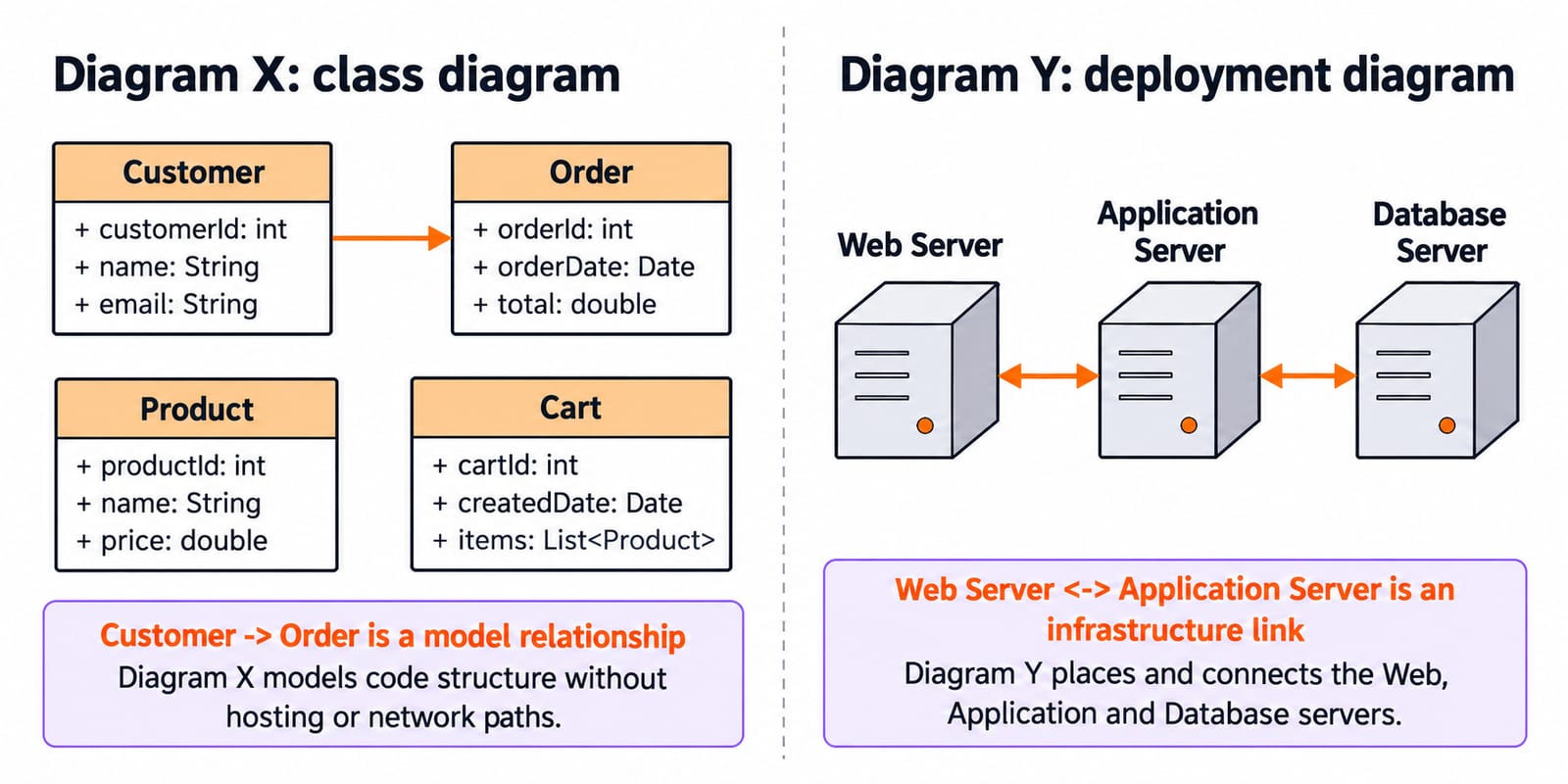
A large e-commerce company is redesigning its system to improve scalability and maintainability. During documentation, two UML diagrams are created:
- Diagram X represents classes such as Customer, Order, Product, and Cart, along with their attributes and relationships.
- Diagram Y represents deployable units such as Web Server, Application Server, and Database Server, including their physical distribution and communication links.
After implementation, the deployment team faces issues in understanding how software components are physically arranged, even though developers claim the system structure is already well-documented using Diagram X.
Determine why Diagram X failed to support deployment understanding and identify which diagram correctly addresses this issue. Justify your answer by analyzing the purpose and limitations of each diagram in the given scenario.
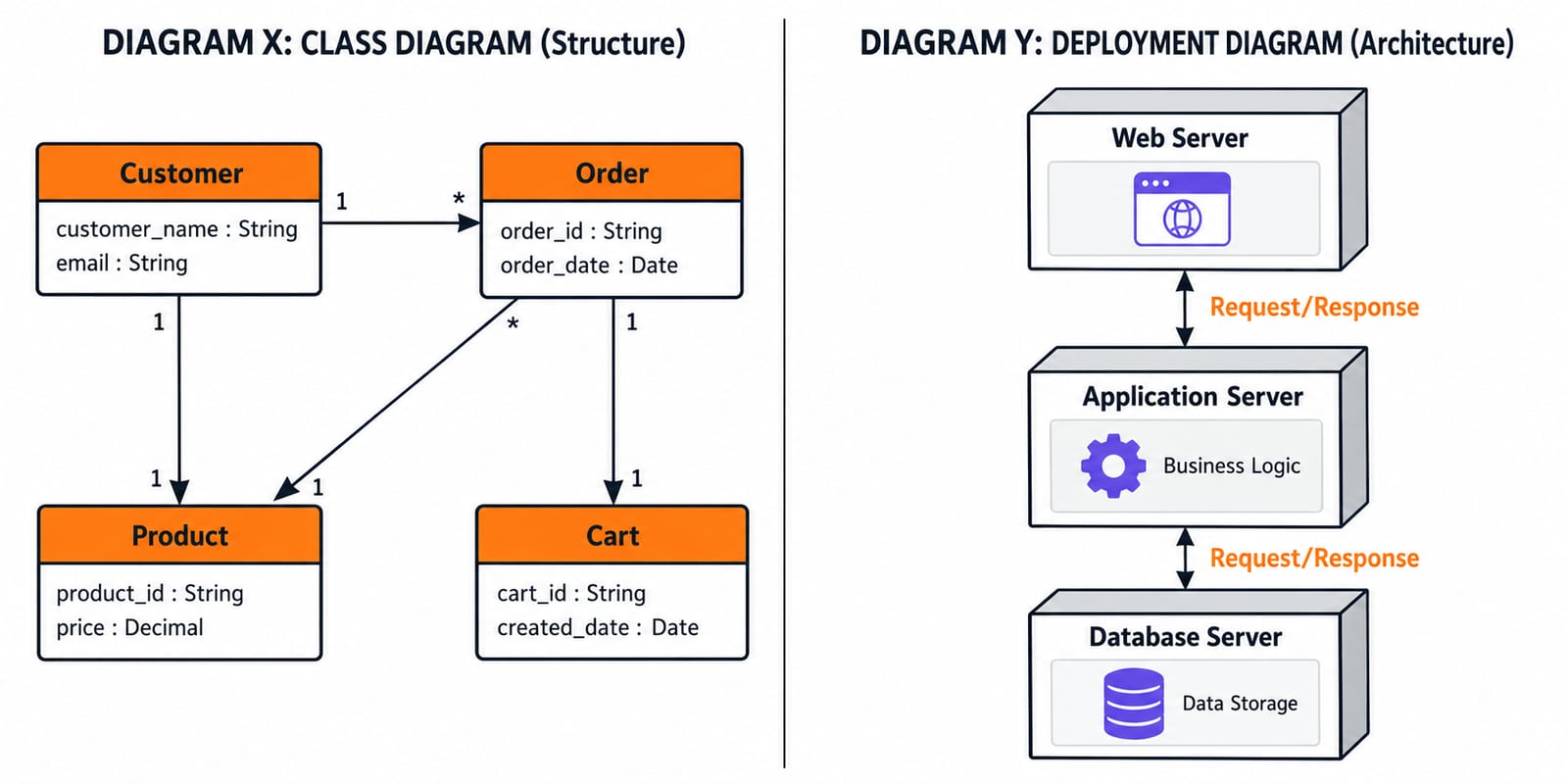
Diagram X is a class diagram: it models code structure without hosting or network paths. Diagram Y is the deployment diagram because it places and connects the Web, Application and Database servers. Customer -> Order is a model relationship; Web Server <-> Application Server is an infrastructure link.
Structural UML practice problem 11: class-level versus component-level architecture
Question 11
A city transport authority is developing a Smart Ticketing System to manage buses, passengers, and payment processing. Two UML diagrams are prepared during the design phase:
- Diagram A shows entities such as Passenger, Ticket, Bus, and Payment, along with their attributes and associations.
- Diagram B shows modules like User Interface Layer, Payment Gateway Module, and Data Storage Unit, including their dependencies and communication paths.
During implementation, developers report confusion: although Diagram A clearly defines objects, it does not help them understand how system components are deployed and interact at a higher level.
Evaluate which diagram is more suitable for representing system architecture and which is appropriate for class-level organization. Justify why relying only on Diagram A leads to incomplete understanding of the system.
Diagram A is a class diagram of entities and associations. Diagram B is a component diagram of modules and dependencies; it becomes a deployment diagram only when nodes or physical placement are added. Payment Gateway Module can provide PaymentPort while User Interface Layer depends on TicketingFacade.
For class and generalisation foundations, continue with OOP for Teaching CS Exams: Classes and Inheritance.
Structural UML diagrams: the next practice step
Redo Questions 1, 4, 7, 8 and 11 without the answers, writing a one-line reason for each choice.
Use the UGC NET CS Test Series for timed practice. Remember: class means types, object means instances, package means logical grouping, component means modules and interfaces, and deployment means nodes and placement.
Keep learning

Data Abstraction Explained: Hide Implementation Details with a Worked Java Example
See how a stable Account contract protects its invariant while the Java implementation changes from a running balance to a transaction ledger.
Updated 16 Nov 20265 min readProgramming Languages Survey

Programming Paradigms Explained: Concepts, Classifications and Worked Examples
Learn how imperative, procedural, object-oriented, functional and declarative styles organise the same computation, and how to classify code from visible evidence.
Updated 15 Nov 20265 min readProgramming Languages Survey
Introduction to Visual Basic (VB): Concepts, Worked Code and Exam Patterns
Learn how a VB.NET form turns text-box input and a button click into a traced result. Then practise operators, loops, procedures, scope and debugging.
Updated 14 Nov 20266 min readProgramming Languages Survey
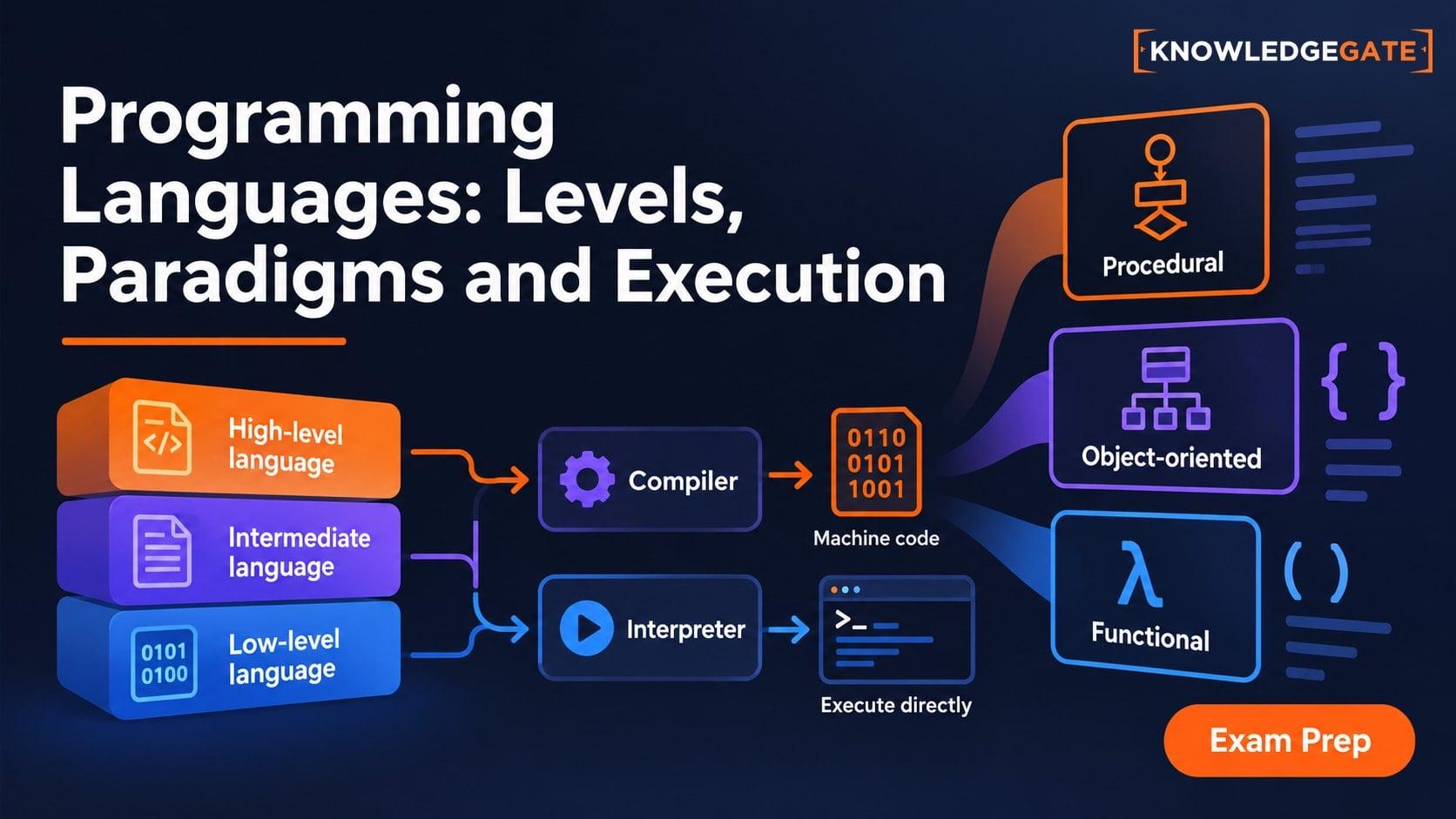
Types of Programming Languages: Levels, Paradigms and Execution Models
Learn why low-level, object-oriented, compiled and dynamically typed describe different axes. Build a clear classification map through one result expressed three ways.
Updated 13 Nov 20266 min readProgramming Languages Survey