Sync Counter Analysis MCQs: 12 Solved GATE, UGC NET and PSC Questions
Solve 12 sync counter analysis questions on modulus, flip-flop count, frequency division and state tracing. Nine are previous-year problems with full working.
KnowledgeGate Team
Exam prep & CS education
Updated 21 Jul 20267 min read

Sync counter analysis questions look small, but they can consume valuable exam time. You have to trace the right state sequence, notice the clock direction or feedback, and avoid a slip in modulus arithmetic. Nine of the twelve questions below come from GATE 2005, UGC NET 2005, 2016 and 2019, UPPSC 2018, HPSC 2021, TPSC 2025 and CDAC CCAT 2025. The other three drill the same modulus and tracing skills. Keep a pen ready and attempt each question before reading its answer.
Related reading: synchronous counter design and ring and Johnson counters.
How to read a sync counter analysis question
Before touching the options, fix five facts:
Modulus and number of bits: An n-bit binary counter has 2^n states, numbered from 0 to 2^n - 1.
Flip-flop type: T, JK and D flip-flops have different next-state rules.
Clock edge: A positive or negative edge tells you exactly when the state updates.
Feedback and gates: These decide whether the circuit is a plain binary counter or a truncated mod-N counter.
Initial state and direction: The start value and up or down direction control every tracing step.
Fix these five, and analysis becomes arithmetic instead of guesswork.
Warm-up: definitions and counting basics
Definitions and powers-of-two arithmetic carry this group. Aim to solve each in under 20 seconds.
Q1. Identify the sequential circuit (UGC NET 2016)
Which of the following is a sequential circuit?
Multiplexer
Decoder
Counter
Full adder
A sequential circuit uses memory, so its output can depend on a past state. A multiplexer, decoder and full adder are combinational circuits whose outputs depend only on their present inputs. A counter stores its current count in flip-flops, so Counter is the correct option.
Q2. What the parallel outputs represent (HPSC 2021)
The parallel outputs of a counter circuit represent the:
parallel data word
clock frequency
counter modulus
clock count
A counter advances as clock pulses arrive, and its Q outputs together hold the current binary count. What that count represents is the clock count: how many clock events have arrived since the last reset. The outputs do not show the clock frequency, and the modulus is fixed by the circuit rather than displayed on the outputs.
Q3. States in a 3-bit binary counter (TPSC 2025)
What is the number of possible states in a 3-bit binary counter?
3
6
8
16
For n bits, the number of possible states is 2^n. Here, 2^3 = 8, giving the states 000, 001, 010, 011, 100, 101, 110 and 111.
Q4. Maximum count in a 4-bit counter (TPSC 2025)
In a 4-bit binary counter, the maximum decimal number that can be represented is
8
15
16
31
Four bits provide 2^4 = 16 different values, but counting begins at 0. The values therefore run from 0 to 2^4 - 1 = 15. In binary, the maximum state is 1111.
Q5. Another name for a mod-10 counter (CDAC CCAT 2025)
A Mod-10 counter is also commonly known as a:
Decade counter
Ring counter
Johnson counter
Up/down counter
A mod-10 counter cycles through ten states, normally 0 to 9. Those ten values form one decimal decade, so this circuit is called a decade counter.
You can practise these patterns in the GATE Test Series. If you want to revise the concept before drilling questions, read Sequential Circuits: Flip-Flops and Counters.
Modulus, flip-flop count and state tables
Two ideas settle the first two questions here: choose the smallest n for which 2^n is at least the required modulus, and multiply the moduli of cascaded counters. The third turns the flip-flop count around, using it to size the state table the circuit is analysed in.
Q6. Flip-flops for a modulo-272 counter (UGC NET 2005)
The number of flip-flops required to design a modulo-272 counter is
8
9
27
11
We need the smallest n such that 2^n >= 272. With eight flip-flops, 2^8 = 256, which is less than 272 and cannot provide enough states. With nine flip-flops, 2^9 = 512, which is at least 272. Therefore, the counter needs 9 flip-flops. Do not read 272 as a clue that the answer must be 27.
Q7. States in a MOD-2 and MOD-5 cascade (UGC NET 2019)
What will be the number of states when a MOD-2 counter is followed by a MOD-5 counter?
5
10
15
20
Cascaded counters multiply their moduli. The combined number of distinct states is 2 x 5 = 10. Adding the two moduli would give 7, but that does not describe all combinations available across the cascade.
Q8. Columns in a state table (UPPSC 2018)
The number of columns in a state table for a sequential circuit with m flip-flops and n inputs is:
m+n
m+2n
2m+n
2m+2n
The table needs m columns for the present state, another m columns for the next state, and n columns for the inputs. The total is m + m + n = 2m + n. Do not confuse columns with rows. The number of input and present-state combinations, and hence the usual row count, is 2^(m+n).
Frequency division
A mod-N counter repeats after N input pulses, so its final output frequency is the input clock frequency divided by N.
Q9. Output frequency of a mod-8 counter
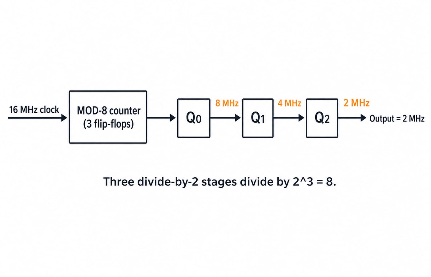
What will be the output frequency of a mod-8 counter which is clocked at 16 MHz clock input signal?
2 MHz
4 MHz
8 MHz
128 MHz
Use output frequency = input frequency / modulus. Therefore, 16 MHz / 8 = 2 MHz. You can also see the three flip-flop stages halving the frequency: 16 MHz becomes 8 MHz, then 4 MHz, then 2 MHz. The 128 MHz option comes from multiplying when the circuit actually divides.
State-sequence tracing
For a repeating counter, reduce the pulse count using pulses mod modulus before tracing. You then need to move only the remainder, not all the original pulses.
Q10. MOD-8 down counter after 27 pulses
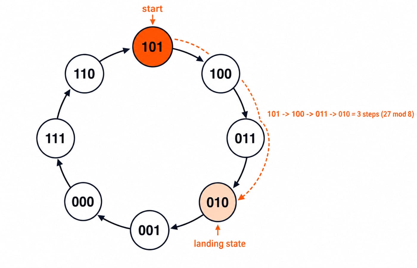
A MOD 8 down counter is provided with initial state 101. The state of the counter after 27 clock pulses will be _______
Answer: 010
A mod-8 counter repeats every eight pulses. Calculate 27 mod 8 = 3, so only three effective steps matter. The initial state 101 is decimal 5. Counting down gives 101 -> 100 -> 011 -> 010. The state after three steps, and therefore after 27 pulses, is 010.
Q11. A custom cycle after 962 pulses
A counter sequence is given as 0-4-7-2-3-1-0-4 ... . If the starting state is (100)2, after application of 962 clock pulse, counter will be at (___)10.
Answer: 2
The repeating cycle is 0-4-7-2-3-1, so its modulus is 6. Convert the starting state first: (100)2 = 4. Now reduce the pulse count: 962 mod 6 = 2 because 962 = 6 x 160 + 2. Move two places along the given cycle, 4 -> 7 -> 2. The final decimal state is 2. The trap is assuming natural binary order instead of following the sequence supplied in the question.
Q12. Pulses to move an 8-bit up counter (GATE 2005)
How many pulses are needed to change the contents of a 8-bit up counter from 10101100 to 00100111 (rightmost bit is the LSB)?
134
133
124
123
Convert both values to decimal. The start value is 10101100 = 128 + 32 + 8 + 4 = 172. The target is 00100111 = 32 + 4 + 2 + 1 = 39. An 8-bit up counter wraps after 256 states, so the pulse count is (39 - 172) mod 256 = (-133) mod 256 = 123.
Check it by tracing the wrap. Moving from 172 to 255 takes 255 - 172 = 83 pulses. One more pulse changes 255 to 0, and 39 more reach 39. The total is 83 + 1 + 39 = 123 pulses.
The same wrap-around arithmetic recurs across the wider flip-flop and counter mix in Sequential Circuits MCQs.
Sync counter questions: three traps that cost marks
Adding moduli instead of multiplying: In Q7, a cascade gives the product of the moduli. Write total states = 2 x 5 before looking at the options.
Tracing every pulse: In Q10 and Q11, a long manual trace creates more chances to miscount. Reduce the pulse count modulo the cycle length, then trace only the remainder.
Ignoring direction or the stated sequence: Q10 counts down, while Q11 follows a custom cycle. Read the direction and actual state list before making the first move.
For definition questions such as Q1, use one quick test: does the circuit need memory of the past? If it does, it is sequential.
How the exam tests this, and your next 20 minutes
Sync counter analysis mixes quick definition, power-of-two, modulus and frequency questions with state-tracing problems. The first group rewards instant recall. The second rewards the pulses mod modulus shortcut and careful reading of the direction or custom state sequence. Timed practice will lock in both skills faster than another passive reading of the theory.
Use the next 20 minutes on timed sync counter practice in the GATE Test Series. If you first need the topic taught end to end, follow GATE Guidance by Sanchit Sir, then use the GATE CS category page to place counters inside the wider subject plan.
The short version is simple: identify the modulus, rule, clock condition, starting state and direction. Reduce long pulse counts before tracing, and write the one-line calculation before selecting an option.
Keep learning
Special Logic Circuits MCQs: 12 Solved Questions on Adders, Encoders, PLA and DAC
Solve 12 special logic circuits MCQs covering recognition, hardware counts, Boolean identities and numerical calculations. Each answer includes the reasoning you should reproduce in an exam.
19 Sep 20268 min read64 viewsDigital Electronics MCQs
Function Equivalence MCQs: 12 Solved Boolean Algebra Problems
Solve 12 function-equivalence questions step by step, from De Morgan's law and absorption to minterm sets, counterexamples and a four-option MSQ.
Updated 17 Sep 20268 min readDigital Electronics MCQs

CLA & Arithmetic Logic MCQs: 10 Solved Questions with Explanations
Solve ten CLA and arithmetic logic MCQs with compact workings for carry equations, timing paths, hardware sizing and operand-pair counting.
Updated 16 Sep 20267 min readDigital Electronics MCQs
Sync Counter Design MCQs: 11 Solved Questions on Modulus, State Sequences and Excitation Logic
Solve 11 synchronous-counter questions covering modulus boundaries, repeated outputs, common-clock tracing, excitation equations, enables and composite states.
Updated 14 Sep 20267 min readDigital Electronics MCQs