

Ripple (Asynchronous) Counters: Worked Counts, Frequency Division and Propagation Delay
Trace a four-bit ripple counter pulse by pulse, calculate divided output frequencies and propagation delay, then see how reset decoding creates a MOD-10 counter.
KnowledgeGate Team
Exam prep & CS education
Updated 30 Oct 20265 min read

Each flip-flop in a ripple counter divides its input frequency by two, but the outputs do not settle together. A four-bit chain exposes the connection among stable count, intermediate states, modulus, divided frequencies and cumulative delay. Counter states use the order Q3Q2Q1Q0, with Q0 as the least significant bit.
1. Ripple counter: what changes asynchronously
In a ripple counter, only the first flip-flop receives the external clock. Each later stage is clocked by the preceding output, so a change travels through the chain. Asynchronous does not mean unclocked. The stages are edge-triggered, but do not share one clock edge.
Consider four negative-edge-triggered JK flip-flops with J=K=1. The external clock drives FF0, then Q0, Q1 and Q2 clock FF1, FF2 and FF3 respectively. Each stage therefore toggles at its falling edge. The broader Sequential Circuits in Digital Electronics: Flip-Flops, Registers and a Worked Mod-4 Counter covers flip-flops, registers and a three-stage ripple sketch; a four-stage ripple analysis adds the full 0-to-15 sequence, MOD-10 reset decoding and cumulative delay.
An n-bit binary ripple counter has 2^n stable states and modulus 2^n. Counting from Q0, output Qk has frequency:
f(Qk) = f_in / 2^(k+1)
This formula is for a complete binary counter. A truncated counter also needs reset analysis.
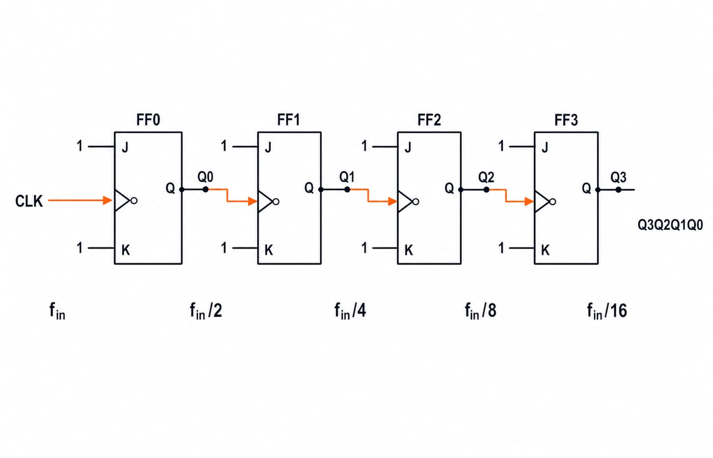
2. Four-bit ripple counter worked example
Start from the clear state 0000. Each external falling edge toggles Q0. A 1 -> 0 transition at Q0 toggles Q1, and the same rule propagates upward.
The counter changes on each pulse:
Pulse 0: cleared state
0000Pulse 1:
Q0rises, giving0001Pulse 2:
Q0falls andQ1rises, giving0010Pulse 3: only
Q0rises, giving0011Pulse 4:
Q0falls, thenQ1falls andQ2rises, giving0100
The stable-state sequence is:
Pulse count | Stable |
|---|---|
0 |
|
1 |
|
2 |
|
3 |
|
4 |
|
5 |
|
6 |
|
7 |
|
8 |
|
9 |
|
10 |
|
11 |
|
12 |
|
13 |
|
14 |
|
15 |
|
16 |
|
The stable value equals the pulse count modulo 16. This convention produces an up-counter. If the active edge or interstage output changes, trace two or three pulses before deciding the direction.
3. Ripple counter as a frequency divider
For f_in = 1 MHz, T_in = 1/f_in = 1 microsecond. Divide by two at every stage:
Output | Frequency calculation | Frequency | Period |
|---|---|---|---|
|
|
|
|
|
|
|
|
|
|
|
|
|
|
|
|
One complete Q3 waveform occupies 16 input periods, so it is divide-by-16. It toggles every eight pulses, but frequency counts full cycles. Every ideal output here has 50% duty cycle, unlike some outputs of a truncated MOD-10 counter.
4. Ripple propagation delay and temporary states
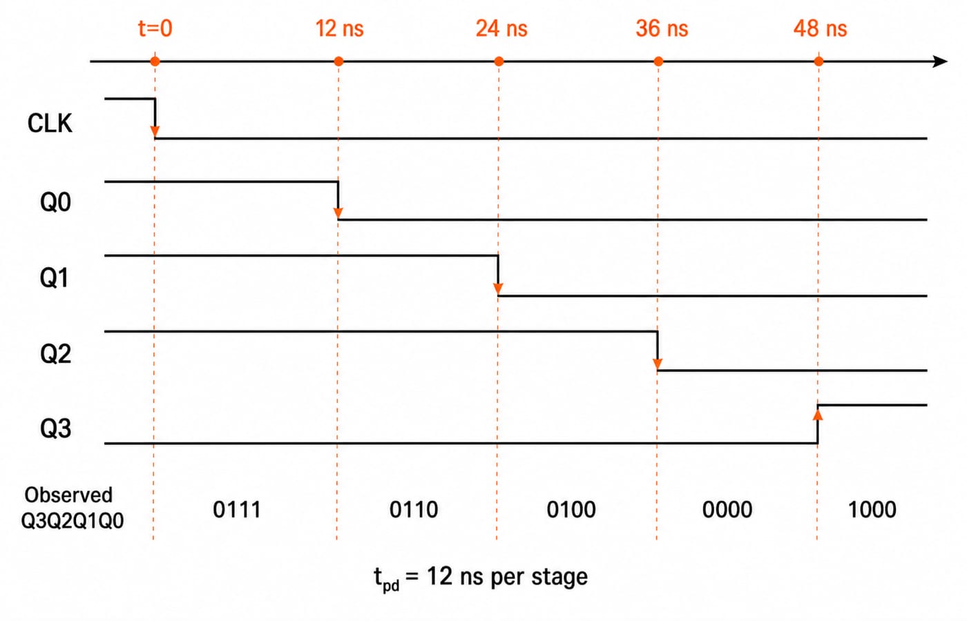
Let every flip-flop have t_pd = 12 ns. Just before the eighth active edge, the state is 0111. After the edge at t=0, the output changes in stages:
Time | Event | Observed state |
|---|---|---|
| No output has responded yet |
|
|
|
|
|
|
|
|
|
|
|
|
|
The worst-case four-stage settling time is 4 x 12 ns = 48 ns. If the parallel count must settle before the next external edge, a first-cut upper bound is:
f_max approximately 1/(48 ns) = 20.83 MHz
A real design keeps margin for setup, reset and decoding delays. During the ripple, a decoder can briefly see 0110, 0100 or 0000, so glitch-sensitive decoding needs timing discipline.
5. MOD-10 ripple counter by reset decoding
A decade counter needs ten stable states. Since 2^3 = 8 is too small and 2^4 = 16 is sufficient, use four stages. Keep 0000 through 1001 for decimal 0 through 9, then reset.
For active-low clear, feed Q3 and Q1 into a NAND gate connected to every asynchronous CLR. After 1001, the ripple attempts 1010. Both inputs are then 1, so the NAND output clears the counter to 0000.
1010 is a brief decoded reset condition, not an eleventh stable count, so the modulus is 10. Gate and reset delays can create a transient, and selected outputs need not retain 50% duty cycle.
6. Ripple counter versus synchronous counter
Feature | Ripple counter | Synchronous counter |
|---|---|---|
Clocking | Only FF0 receives the external clock | Every flip-flop receives the same external edge |
State change | Travels from stage to stage | Begins together at the shared edge |
Worst-case path | Roughly | Does not accumulate clock-to-Q delay stage by stage |
Decoding | Can see temporary states | No ripple sequence, though logic still needs settling time |
Hardware | Very simple | Requires next-state logic |
Typical use | Low-speed counting and division | Faster, cleaner parallel counting |
The four-stage ripple path took 48 ns with 12 ns devices. A synchronous design does not multiply clock-to-Q delay by four in the same way, although its combinational next-state logic still has delay. Use Sync Counter Analysis MCQs to practise that contrast through questions.
7. Ripple counter exam patterns and common traps
Most questions reduce to four tasks:
Derive width or modulus. Four binary stages give MOD-16 unless reset logic truncates the sequence.
Trace direction from the stated active edge and
Qor complemented-output connection.Divide frequency stage by stage. Here
1 MHzbecomes62.5 kHzatQ3.Accumulate the longest delay. Here
4 x 12 ns = 48 ns.
Place these skills in the broader GATE CS Exam Preparation syllabus, without assuming every question uses the same convention.
Remember that asynchronous does not mean clockless, bits do not change together, and 1010 is not stable when it triggers clear. Also, f_in/16 is Q3 waveform frequency, not its toggle rate. Direction requires the edge and interstage connection.
Use this 20-second check: write Q3Q2Q1Q0, mark the active edge, trace three pulses, compute 2^n or identify the reset state, divide frequency stage by stage, then multiply the longest ripple path by t_pd. Follow it with Sequential Circuits MCQs: 11 Solved Flip-Flops for immediate practice.
8. Ripple counters: the short version and next step
A ripple counter gets binary counting and repeated divide-by-two behaviour with little logic, but every stage waits for the previous output. That makes propagation delay and decoding glitches grow down the chain. The key results are MOD-16 for four bits, Q3=62.5 kHz from 1 MHz, 48 ns worst-case settling with 12 ns per stage, and MOD-10 by clearing on 1010.
Redraw the four-stage chain from memory and reproduce the 0111 -> 1000 timing before attempting mixed counter questions. If you want Digital Logic sequenced with the rest of GATE CS, GATE Guidance by Sanchit Sir is the structured next step.
Go deeper with the full courseDigital Electronics
Keep learning

Ripple Counter MCQs: 12 Solved Questions on Modulus, States and Delay
Solve 12 ripple counter MCQs by reading the clock chain, calculating modulus and state movement, and adding propagation delays correctly.
Updated 30 Oct 20267 min read70 viewsDigital Electronics MCQs

Shift Registers, Ring and Johnson Counters for GATE: Frequency Division and Timing Numericals Solved
Build a 4-bit ring counter and Johnson counter state by state, then use their mod values to solve frequency-division and maximum-clock questions.
Updated 29 Jul 20265 min read60 viewsDigital Logic

Transmission and Propagation Delay for GATE
Separate the time needed to put a packet on a link from the time needed for its bits to travel. Then solve delay, pipe-capacity and utilisation questions without unit mistakes.
Updated 30 Oct 20266 min read228 viewsGATE Strategy & Roadmap
Division Operator in Relational Algebra: Worked DBMS Example and Exam Traps
Learn relational division by solving one student-course dataset three ways, then test your understanding against extra tuples, duplicates, and an empty divisor.
Updated 19 Nov 20265 min readDBMS