Shift Registers, Ring and Johnson Counters for GATE: Frequency Division and Timing Numericals Solved
Build a 4-bit ring counter and Johnson counter state by state, then use their mod values to solve frequency-division and maximum-clock questions.
KnowledgeGate Team
Exam prep & CS education
Updated 29 Jul 20265 min read
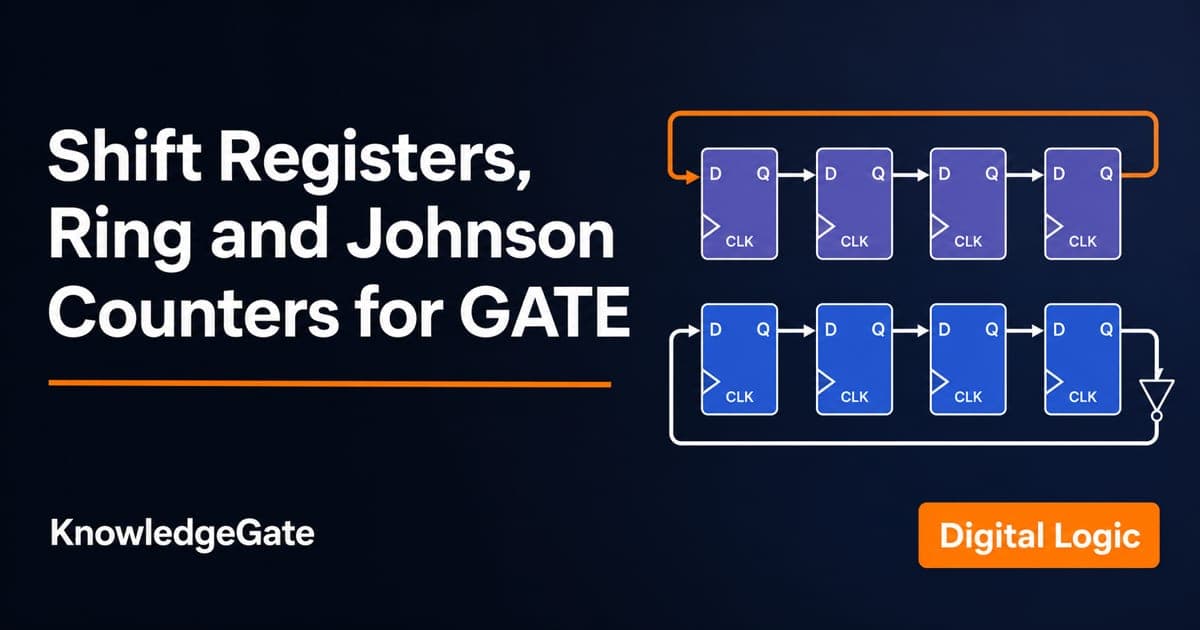
Ring and Johnson counters look like facts to memorise, until a GATE question changes the initial state or asks for an output frequency. Both are shift registers with feedback, so drawing the state sequence gives you the mod value and frequency division.
1. The shift register under ring and Johnson counters
A shift register is a chain of flip-flops on a common clock. Each active edge moves every stored bit by one position. Input and output arrangements create four familiar types:
Type | Input | Output | Typical use |
|---|---|---|---|
SISO | Serial | Serial | Delay a bit stream |
SIPO | Serial | Parallel | Serial-to-parallel conversion |
PISO | Parallel | Serial | Parallel-to-serial conversion |
PIPO | Parallel | Parallel | Temporary parallel storage |
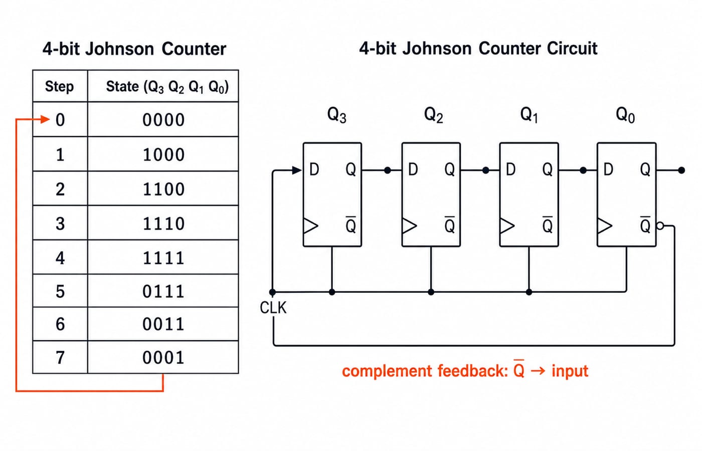
The counter versions add a feedback connection. A ring counter sends the final stage's Q output directly to the first stage's input. A Johnson counter sends the complement, Q-bar, back instead. That one inversion changes the number and shape of the valid states.
If flip-flop behaviour needs a quick revision first, use the sequential circuits, flip-flops and counters guide. For this topic, keep one clean pair in mind: ring means Q feedback, Johnson means Q-bar feedback.
2. The 4-bit ring counter: state table and divide-by-4
Preset a 4-bit ring counter to 1000. The single 1 moves by one place on every clock:
Clock edge | Q3 Q2 Q1 Q0 |
|---|---|
0 | 1000 |
1 | 0100 |
2 | 0010 |
3 | 0001 |
4 | 1000 |
The state at edge 4 is the starting state, so there are four distinct states. The counter is MOD-4. Any one Q line repeats its pulse once every four input clock periods, which makes its repetition frequency fclock / 4.
For a 16 MHz clock:
Number of states = 4.
Output repetition frequency =
16 MHz / 4.Output repetition frequency = 4 MHz.
An n-bit ring counter provides n states, not 2^n. Its simple one-hot decoding compensates partly for that low state count.
The preset matters. Starting at 0000 remains at 0000, outside the intended one-hot loop. Questions about self-starting circuits test this weakness.
3. The 4-bit Johnson counter: state table and divide-by-8
Now complement the last output before feeding it back. Starting from 0000, 1s fill the register and then drain from it:
Clock edge | Q3 Q2 Q1 Q0 |
|---|---|
0 | 0000 |
1 | 1000 |
2 | 1100 |
3 | 1110 |
4 | 1111 |
5 | 0111 |
6 | 0011 |
7 | 0001 |
8 | 0000 |
There are eight distinct states before repetition. A 4-bit Johnson counter is therefore MOD-8, and an n-bit Johnson counter has 2n valid states. The complement feedback produces a filling half and an emptying half, which is why its useful state count is twice that of the ring counter.
With the same 16 MHz input:
Number of states =
2 x 4 = 8.Output frequency =
16 MHz / 8.Output frequency = 2 MHz.
Four flip-flops therefore give four ring states and eight Johnson states, and the rule scales: n flip-flops, n ring states, 2n Johnson states.
4. Frequency division at a glance
Every MOD-k counter needs k input clocks for a full state cycle, so its cycle frequency is fclock / k. Count the actual distinct states before applying that rule.
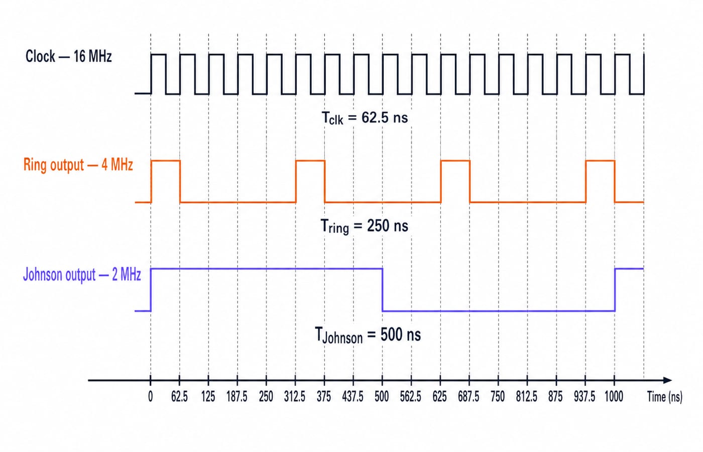
With a 16 MHz clock, the same two answers follow from the periods:
Ring period =
4 x (1/16 MHz) = 250 ns, so frequency =1/250 ns = 4 MHz.Johnson period =
8 x (1/16 MHz) = 500 ns, so frequency =1/500 ns = 2 MHz.
The two independent calculations agree with the state-count method. This is also a useful unit check: more states per cycle must mean a lower output frequency for the same clock.
5. A timing numerical: maximum clock frequency
Frequency-division questions ask what the counter does to the clock. Timing questions ask how fast the hardware itself can be clocked. In a shift register, data leaving one flip-flop must reach the next stage and settle there before the following active edge, which puts a floor under the clock period:
Tclock >= tpd + tsetup
Suppose each flip-flop has propagation delay tpd = 8 ns and setup time tsetup = 2 ns.
Minimum clock period =
8 ns + 2 ns = 10 ns.Convert to seconds:
10 ns = 10 x 10^-9 s = 10^-8 s.Maximum frequency =
1 / 10^-8 s = 10^8 Hz.Therefore, fmax = 100 MHz.
A 16 MHz operating clock has a period of 62.5 ns, which is longer than the 10 ns minimum, so it satisfies this timing bound. In a fuller hardware problem, use every delay or clock-skew term supplied in the question. Do not silently add hold time to a setup-time expression when the question does not require it.
6. The traps GATE builds these on
The recurring mistakes are small but costly:
Swapping n and 2n. Ring has n valid states; Johnson has 2n.
Calling a ring counter MOD-
2^n. That is the binary-counter result.Ignoring initialisation. A basic ring counter can remain trapped at all zeroes.
Dividing by the number of flip-flops before counting the circuit's actual states.
Mixing nanoseconds and megahertz. Convert the period to seconds, or remember that
1/10 ns = 100 MHzonly after checking the power of ten.Multiplying all stage delays for a synchronous shift register. Every stage is clocked together, so the timing path is the single hop from one flip-flop to the next.
About 1,500 Digital Electronics questions are available for practice across this area. Use the Digital Electronics sequential-circuits MCQ set to test state tracing before moving to mixed timed papers.
7. How GATE tests this and the official pointer
GATE commonly turns the topic into three tasks: find the number of flip-flops needed for a stated mod value, compute an output frequency from a state cycle, or find the maximum clock frequency from propagation and setup data. The circuit diagram may look unfamiliar, but the solution remains the same: identify the feedback, list states, count the cycle and then calculate.
Digital Electronics belongs to the GATE subject list, but its exact marking pattern must come from the organising IIT's official GATE portal for the relevant cycle. The GATE category helps place this topic inside the wider preparation path, while GATE Guidance by Sanchit Sir connects it with the rest of Digital Logic.
8. The short version and your next step
A ring counter uses Q feedback, has n states and divides the clock by n. A Johnson counter uses Q-bar feedback, has 2n states and divides the clock by 2n. For the 4-bit examples, 16 MHz becomes 4 MHz and 2 MHz respectively. With an 8 ns propagation delay and 2 ns setup time, the minimum period is 10 ns and the maximum frequency is 100 MHz.
Draw both state tables once without looking. Then use the GATE Test Series to practise the same rules under time, including circuits where the initial state or feedback path is less obvious.
Keep learning

Functional Completeness in Digital Logic: NAND, NOR and Worked Examples
Learn what makes a Boolean operator set complete, how NAND and NOR recover a standard basis, and how to verify a four-gate NAND construction.
Updated 2 Oct 20266 min readDigital Logic
Boolean Function Counts: Formulas, Worked Examples and Exam Traps
Build the master Boolean-function formula from output choices, then learn how common restrictions change the count through combinations, pairing and inclusion-exclusion.
Updated 27 Sep 20266 min readDigital Logic

Analog-Digital Conversion Basics: ADC, DAC, Worked Examples and Exam Patterns
Build ADC and DAC basics from one consistent transfer model, then practise code selection, reconstruction error, flash and SAR conversion, and bit-depth calculations.
Updated 25 Sep 20266 min readDigital Logic

Universal Realization with NAND and NOR Gates: Concepts, Worked Example and Exam Patterns
Learn why NAND and NOR are universal, then implement one three-variable function using four NAND gates and four NOR gates with verified input traces.
Updated 23 Sep 20265 min readDigital Logic