

Ring and Johnson Counters Explained: 4-Bit State Sequences, Timing and Exam Traps
Trace both 4-bit feedback counters edge by edge, then calculate their state counts, waveforms, output frequencies, duty cycles and decoded phases.
KnowledgeGate Team
Exam prep & CS education
Updated 29 Oct 20265 min read

Both circuits use four flip-flops and one feedback loop, but a single inversion changes their state counts, legal seeds, waveforms and decoding. With states written as Q3 Q2 Q1 Q0 and sampled on an 800 kHz rising-edge clock, a ring counter recirculates Q3 while a Johnson counter feeds back Q3'. That feedback rule determines the exact 4-bit state sequences, output frequencies, duty cycles, decoded phases and unused-state behaviour.
1. Ring and Johnson counters are feedback shift registers
Both are synchronous shift-register counters. Four positive-edge-triggered D flip-flops share one clock, and the pattern shifts once per rising edge. In a ripple counter, one flip-flop output clocks another.
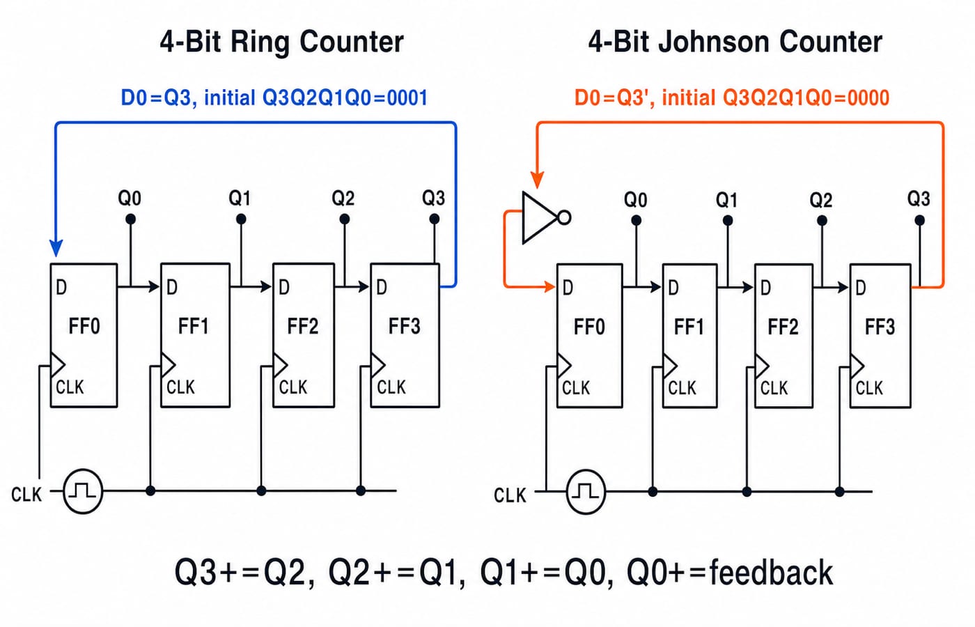
A state is written as Q3 Q2 Q1 Q0. Every edge applies these simultaneous updates:
Q3(next)=Q2, Q2(next)=Q1, Q1(next)=Q0, Q0(next)=feedback
The ring uses feedback=Q3 and recirculates its pattern. The Johnson, or twisted-ring, counter uses feedback=Q3', so ones fill the register and zeros empty it. Frequency-division and propagation/setup timing numericals, using the opposite written shift direction, are worked separately in Ring and Johnson Counters: GATE Numericals Solved. Reversing the written shift direction reverses the printed state sequence, but not the state count, output frequency or duty cycle.
2. Why an n-bit ring has n states but a Johnson counter has 2n
A one-hot ring has one 1 in n positions, giving n intended states. A cleared Johnson counter takes n edges to fill with ones and n to empty, giving 2n states. Neither uses all 2^n patterns.
For MOD-12, a ring needs n=12 flip-flops. A Johnson counter has 2n=12, hence n=6. A binary MOD-12 counter fits in four flip-flops but needs different next-state and reset logic.
Load the ring with 0001; 0000 locks because zero returns forever. The Johnson may start at 0000, because old Q3=0 makes Q3'=1 at edge 1. Without recovery logic, neither is self-starting or self-correcting.
3. Build the exact 4-bit circuits before tracing them
Use FF0 to FF3, with outputs Q0 to Q3. In both circuits, connect D1=Q0, D2=Q1 and D3=Q2. Connect D0=Q3 for the ring, but D0=Q3' for the Johnson counter. All clock pins share the same rising-edge clock.
Preset and clear controls load ring state Q3 Q2 Q1 Q0=0001; the Johnson stages clear to 0000. After release, these asynchronous controls stay inactive, and ideal states change only on rising edges. The CS Fundamentals for Exams & Placements route gives the broader Digital Logic context.
4. Worked ring-counter trace: four states, one-hot outputs
The loaded ring state is 0001 at k=0, and state k is the state immediately after edge k.
Edge | State after edge | Feedback sampled at edge | Active one-hot output |
|---|---|---|---|
0 |
| loaded state, no edge yet |
|
1 |
|
|
|
2 |
|
|
|
3 |
|
|
|
4 |
|
|
|
5 |
|
|
|
6 |
|
|
|
7 |
|
|
|
8 |
|
|
|
From old 1000, the next tuple is (Q2,Q1,Q0,Q3)=(0,0,0,1)=0001. Never move new Q0 through several stages on one edge. All stages sample old inputs together.
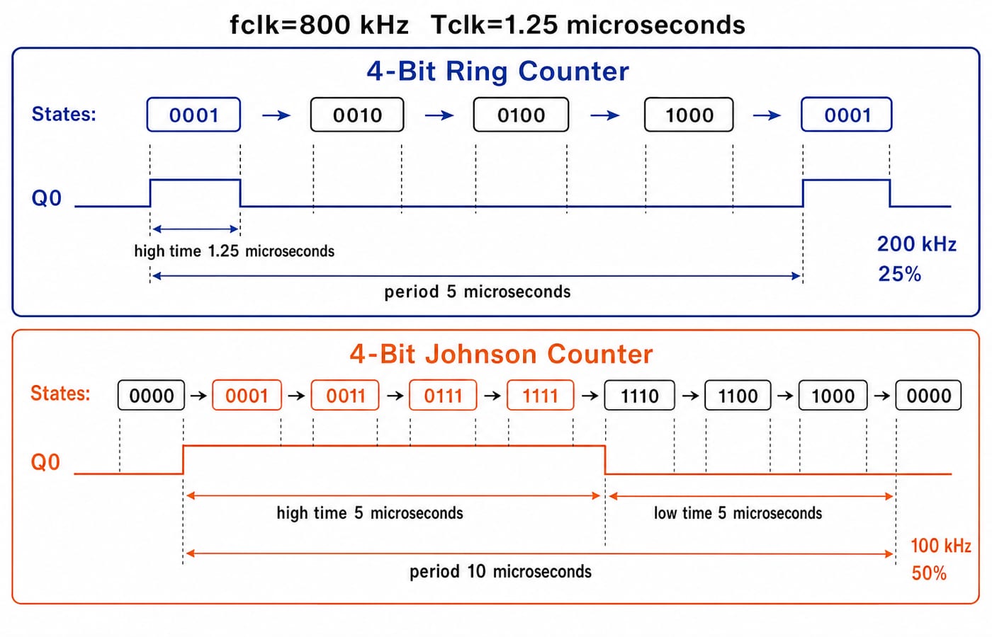
At f_clk=800 kHz, T_clk=1/800 kHz=1.25 microseconds. Q0 is high for one clock in four: high time 1.25 microseconds, period 5 microseconds, f_Q0=200 kHz, duty cycle 25%. Other outputs match with one-clock phase offsets.
5. Worked Johnson-counter trace: eight states from four flip-flops
Starting at 0000, feedback is the complement of old Q3 entering Q0.
Edge | State after edge | Feedback sampled at edge |
|
|---|---|---|---|
0 |
| loaded state, no edge yet | 0 |
1 |
|
| 1 |
2 |
|
| 1 |
3 |
|
| 1 |
4 |
|
| 1 |
5 |
|
| 0 |
6 |
|
| 0 |
7 |
|
| 0 |
8 |
|
| 0, cycle repeats |
Edges 1 to 4 shift in ones until 1111; edges 5 to 8 shift in zeros until 0000. From old 1111, (Q2,Q1,Q0,Q3')=(1,1,1,0)=1110.
Here Q0 is high for four clocks and low for four: high time 4 x 1.25=5 microseconds, period 10 microseconds, frequency 100 kHz, duty cycle 50%. State count is not the number of high intervals.
6. Decode phases, jump to a later edge and recognise unused states
Ring outputs identify their one-hot phases directly. Johnson phases need two-literal decoders:
Phase | State | Decoder | Phase | State | Decoder |
|---|---|---|---|---|---|
|
|
|
|
|
|
|
|
|
|
|
|
|
|
|
|
|
|
|
|
|
|
|
|
Check S2: Q2'Q1=1 only at 0011 within this eight-state cycle.
After edge 11, the ring uses 11 mod 4=3, giving 1000; the Johnson uses 11 mod 8=3, giving 0111. Fix the seed and direction before using this shortcut.
Four flip-flops encode 16 patterns. The ring uses 4, leaving 12 outside; 0000 and 1111 lock, while others rotate in separate cycles. The Johnson uses 8, and the other 8 form another cycle. Recovery needs extra detection and logic.
7. Ring and Johnson counter traps and representative exam question forms
Tempting shortcut | Why it fails | Correct check |
|---|---|---|
Ring has | One-hot uses | Count seed rotations |
Johnson has | Fill and empty take | Use |
Seed ring with | Zero locks | Preset one-hot |
Return | That is ring feedback | Return |
Reverse bit order | Shift appears reversed | Keep |
Update stages serially | Sampling is simultaneous | Use old values |
Unused states self-correct | Alternate cycles persist | Add recovery logic |
State count fixes duty cycle | High time varies by output | Trace that output |
Typical exam questions ask for the feedback connection, next state, state after k edges, required flip-flops, output frequency, duty cycle, phase decoder or lockout condition. Synchronous counter problems use the same simultaneous-update discipline but derive next states from excitation logic.
Practise the same reasoning with Sequential Circuits MCQs: 11 Solved GATE Questions, then use GATE Test Series: Mocks & Topic-wise Tests for a timed check.
8. Ring versus Johnson counters: the short version and next step
Use this retrieval checklist:
Fix the order
Q3 Q2 Q1 Q0and the shift rule.Inspect whether feedback is
Q3orQ3'.Load the correct seed.
Trace until the first repeated state.
Only then calculate modulus, frequency, duty cycle or decoded phase.
Reproduce both cycles from memory, then verify the anchors 1000 -> 0001 for the ring and 1111 -> 1110 for the Johnson counter. At 800 kHz, recover ring f_Q0=200 kHz, 25% and Johnson f_Q0=100 kHz, 50%.
For a sequenced Digital Logic study path, continue with GATE Guidance by Sanchit Sir. Redo the two state tables first, then move to counter-design problems.
Go deeper with the full courseDigital Electronics
Keep learning

Shift Registers, Ring and Johnson Counters for GATE: Frequency Division and Timing Numericals Solved
Build a 4-bit ring counter and Johnson counter state by state, then use their mod values to solve frequency-division and maximum-clock questions.
Updated 29 Jul 20265 min read60 viewsDigital Logic

Ring and Johnson Counter MCQs: 10 Solved Questions with Explanations
Solve ten published ring and Johnson counter questions, then check each answer through state models, binary traces and compact exam-ready rules.
Updated 7 Sep 20267 min read105 viewsDigital Electronics MCQs
Shift Registers Explained: Types, Timing and a 4-Bit Worked Trace
Learn one reliable method for tracing shift registers. Fix the bit order, apply simultaneous next-state equations, and follow a complete four-clock example.
Updated 4 Sep 20266 min read92 viewsDigital Logic

Synchronous Counter Analysis: Two Worked State Sequences for GATE
Analyse two three-bit synchronous counters step by step. One produces a binary MOD-8 sequence, while the other shows how unused states can trap a circuit.
Updated 21 Aug 20265 min read61 viewsDigital Logic