Multiplexers (MUX): Selection Logic, Boolean Function Realization and GATE Worked Examples
Learn how a MUX selects data, realizes Boolean functions, and scales through cascading. Trace two exact circuits and repair the mistakes that usually change the answer.
KnowledgeGate Team
Exam prep & CS education
Updated 20 Sep 20265 min read71 views

A multiplexer makes one decision: the select bits form a binary index, and the indexed data input reaches the output. Reading 10 as the second wire instead of index 2, reversing selector order, or ignoring enable polarity changes the result. The same index rule governs 4:1 traces, Boolean-function wiring and cascaded MUXes.
Related reading: MUX function implementation and Multiplexer MCQs.
Multiplexer fundamentals: one selected input, one output
A multiplexer, or MUX, is a combinational many-to-one data selector. With n select lines, it can address 2^n data inputs. A 2:1 MUX needs one selector, a 4:1 needs two, and an 8:1 needs three.
Keep four roles separate: data inputs carry values, select inputs choose an index, the output carries that value, and an optional enable controls operation. MUXes belong to the wider Digital Logic route covered in CS Fundamentals for Exams & Placements.
Use + for OR, adjacency for AND, and an apostrophe for complement. For a 2:1 MUX, the selector equation is:
Y = S'I0 + SI1
At S=0, this becomes Y=(1)I0+(0)I1=I0. At S=1, it becomes Y=(0)I0+(1)I1=I1. With an active-high enable E, the equation is Y=E(S'I0+SI1). An enable bubble on a symbol instead indicates active-low control.
For a 4:1 MUX, let S1 be the more significant selector bit and S0 the less significant bit:
Y = S1'S0'I0 + S1'S0I1 + S1S0'I2 + S1S0I3
For every selector value, exactly one selector product equals 1, so only one data input reaches Y.
A 4:1 MUX worked example: trace every selector value
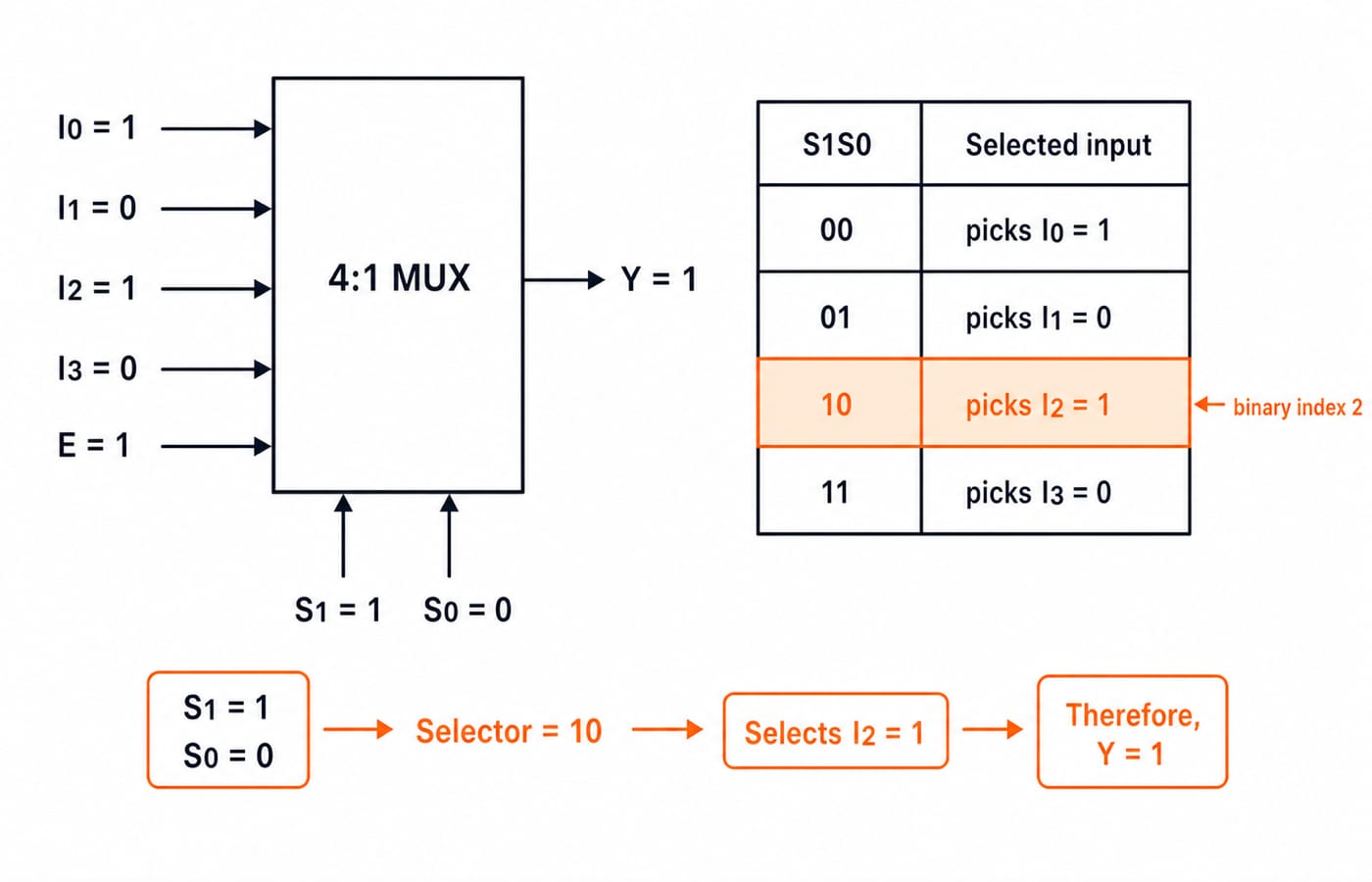
Take an active-high MUX with E=1 and (I0,I1,I2,I3)=(1,0,1,0).
S1S0 | Selected input | Y |
|---|---|---|
|
|
|
|
|
|
|
|
|
|
|
|
The selector 10 is binary index 2, so it selects I2, not the second item counted visually.
Now substitute S1=1 and S0=0 into the equation:
Y=(0)(1)(1) + (0)(0)(0) + (1)(1)(1) + (1)(0)(0)
Y=0+0+1+0=1
The table and algebra agree. Under this active-high convention, E=0 forces Y=0 regardless of the data. If your table and equation disagree, inspect the S1S0 order and enable polarity before changing data values.
Boolean function realization with a 4:1 MUX
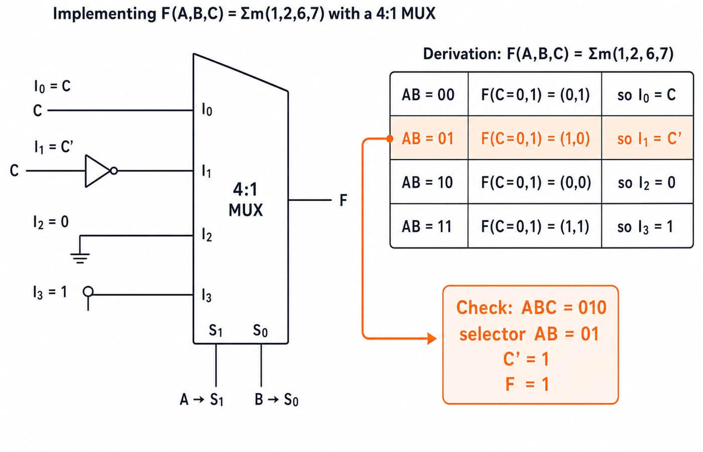
Consider F(A,B,C)=Σm(1,2,6,7). Choose A=S1 and B=S0, then hold each AB pair fixed while C changes from 0 to 1.
AB | F at C=0, C=1 | Required data input |
|---|---|---|
|
|
|
|
|
|
|
|
|
|
|
|
Pair 00 covers m0,m1. Only m1 is present, giving (0,1)=C. For m2,m3, only m2 is present, giving (1,0)=C'. Neither m4 nor m5 is present, so 10 gives 0. Both m6 and m7 are present, so 11 gives 1.
Three direct checks confirm the wiring:
ABC=001selectsI0=C=1, soF=1.ABC=010selectsI1=C'=1, soF=1.ABC=011selectsI1=C'=0, soF=0.
Choose n-1 variables as selectors for a 2^(n-1):1 MUX. Inspect the remaining variable across each pair, then assign its data input from {0,1,X,X'}. The Boolean Algebra and K-map Minimization Guide helps when you want to simplify before hardware realization.
Cascading MUXes: build and trace an 8:1 selector
Build an 8:1 selector from two 4:1 MUXes and one 2:1 MUX. Feed D0-D3 into the lower block and D4-D7 into the upper block. Connect S1,S0 to both. Their outputs feed the 2:1, where S2=0 chooses the lower group and S2=1 the upper.
Use the vector (D0,D1,D2,D3,D4,D5,D6,D7)=(0,1,0,0,1,0,1,1) at S2S1S0=110. The shared local selector is S1S0=10. The lower block therefore produces D2=0, while the upper block produces D6=1. Since S2=1, the final stage chooses the upper result, giving Y=D6=1.
For the global check, binary 110 equals decimal 6, so the circuit must return D6. Both routes give 1.
MUX, decoder and demultiplexer: do not confuse selection direction
These blocks use binary codes differently. A shared index does not make them interchangeable.
Block | Data direction | Selector or code role | Example at code 10 |
|---|---|---|---|
| Four inputs to one output | Chooses an input | Reads |
| Code to one active output | Decodes the input code | Asserts |
| One input to four outputs | Chooses an output path | With |
Adder | Inputs to a new arithmetic result | No routing selection | Computes a sum |
For deeper decoder, DeMUX and encoder treatment, use DeMUX, Decoder and Encoder Explained: Truth Tables, Worked Circuits and Exam Traps. That earlier article owns code-to-line decoding, data routing to an output, and line-to-code encoding; this section only contrasts those directions with a MUX's many-to-one input selection.
Multiplexer mistakes: why the answer changes and how to repair it
Mistake | What goes wrong | Repair |
|---|---|---|
Selector reversal |
| Write |
Local and global indices mixed | Local | Label it local input |
Enable polarity ignored | A bubbled enable is treated as active-high | Mark the asserted level before tracing |
Truth table grouped wrongly | The data inputs no longer reproduce the minterms | For selectors |
Don't-care forced to zero | A valid simplification opportunity is lost | Choose each don't-care as |
A don't-care symbol is not automatically 0. If a problem also names an ordinary variable X, label the don't-care separately, such as d, so the two meanings cannot be confused.
How GATE-style questions test multiplexers
Representative questions ask you to trace Y, derive inputs for a Boolean function, count selectors, build a larger MUX, or compare MUX and decoder realizations. Selector order, enable polarity and permitted block size are the constraints to mark beside the circuit before tracing it.
A 16:1 MUX needs log2(16)=4 select lines. Using only 4:1 blocks, four first-level MUXes select within D0-D3, D4-D7, D8-D11, and D12-D15 through S1,S0. One final 4:1 selects among their outputs through S3,S2. Total: 4+1=5 blocks.
For a quick verification routine, convert the selector to a binary index, check enable polarity, label the chosen input, and test one truth-table row after realizing a function. Then use Combinational Circuits MCQs: 12 Solved MUX and Adders for follow-on practice.
Multiplexers: the short version and next step
Revision card: n selectors address 2^n inputs, a MUX routes a selected value, and S1S0=10 selects index 2. On a 4:1 MUX, every selector pair reduces the remaining variable to 0,1,C, or C'.
Now reproduce four checkpoints without looking. The 4:1 trace at 10 gives I2=1. The function Σm(1,2,6,7) maps to (I0,I1,I2,I3)=(C,C',0,1). The 8:1 cascade at 110 returns D6=1. A 16:1 circuit built only from 4:1 blocks needs five blocks. Any mismatch tells you exactly which section to revisit.
Use GATE Guidance by Sanchit Sir when you want Digital Logic sequenced inside a wider GATE preparation route. If only this concept is weak, rework the two exact examples and then attempt the linked MUX practice set.
Keep learning

Functional Completeness in Digital Logic: NAND, NOR and Worked Examples
Learn what makes a Boolean operator set complete, how NAND and NOR recover a standard basis, and how to verify a four-gate NAND construction.
Updated 2 Oct 20266 min readDigital Logic
Boolean Function Counts: Formulas, Worked Examples and Exam Traps
Build the master Boolean-function formula from output choices, then learn how common restrictions change the count through combinations, pairing and inclusion-exclusion.
Updated 27 Sep 20266 min readDigital Logic

Analog-Digital Conversion Basics: ADC, DAC, Worked Examples and Exam Patterns
Build ADC and DAC basics from one consistent transfer model, then practise code selection, reconstruction error, flash and SAR conversion, and bit-depth calculations.
Updated 25 Sep 20266 min readDigital Logic

Universal Realization with NAND and NOR Gates: Concepts, Worked Example and Exam Patterns
Learn why NAND and NOR are universal, then implement one three-variable function using four NAND gates and four NOR gates with verified input traces.
Updated 23 Sep 20265 min readDigital Logic