DeMUX, Decoder and Encoder Explained: Truth Tables, Worked Circuits and Exam Traps
Follow binary 101 through a decoder, a DeMUX and an encoder, then use the same logic to realise a Boolean function and solve common exam checks.
KnowledgeGate Team
Exam prep & CS education
Updated 11 Sep 20266 min read
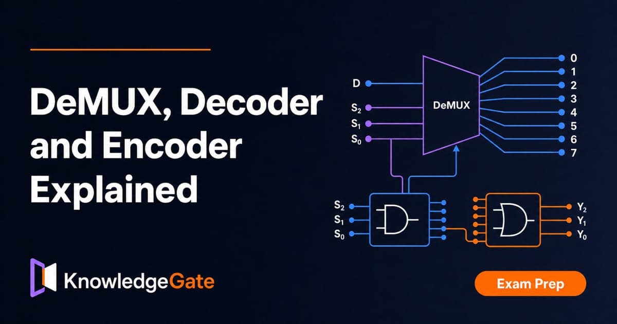
A decoder, a demultiplexer and an encoder can show the same binary code, yet they perform three different jobs. Memorising input and output counts is not enough. You may connect data to a select pin, reverse the encoder direction or miss an active-low output.
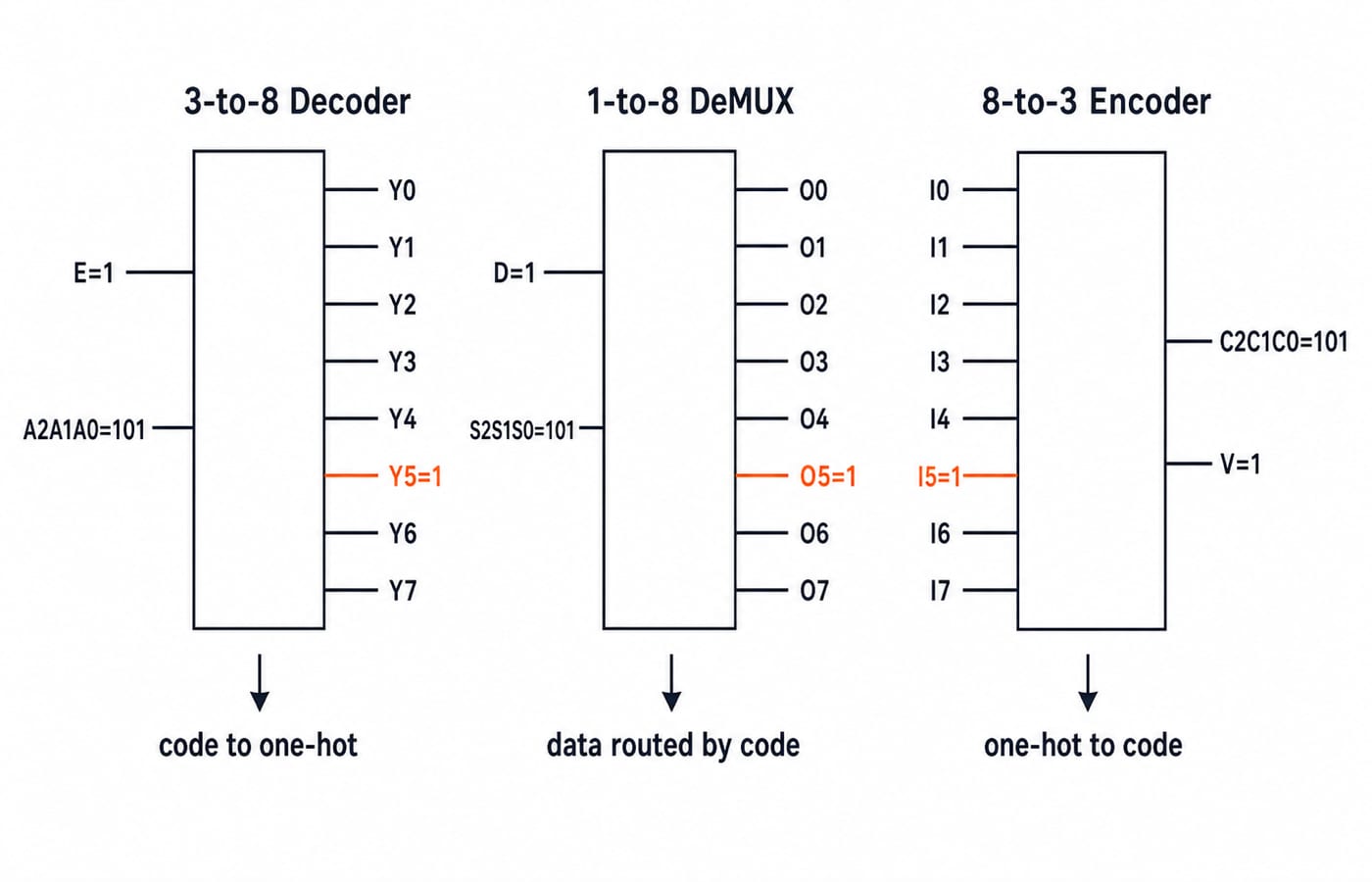
Binary 101 names line 5: a decoder activates it, a DeMUX routes data to it, and an encoder returns the same code when input I5 alone is active. Exact minterms realise a Boolean function, while a cascade trace determines both device count and the selected global output.
Related reading: decoder and encoder MCQs and multiplexers.
1. DeMUX, decoder and encoder: three jobs, one comparison
Block | Data path | Control or code lines | Output meaning | Assumption |
|---|---|---|---|---|
| No separate data input |
| One output named by the code becomes active | One-hot output |
| One data input |
| Selected output receives the data value | One selected destination |
| One of |
| Code gives the active input's index | Exactly one input active |
Three-bit inputs run from most-significant to least-significant bit as A2 A1 A0 or S2 S1 S0. Lines are numbered 0 to 7. Under the active-high convention used for the line-5 trace, the selected output is 1 and every other output is 0.
Block | Applied condition | Result |
|---|---|---|
3-to-8 decoder | E=1, A2A1A0=101 | Y5=1; Y0-Y4, Y6 and Y7 are 0 |
1-to-8 DeMUX | D=1, S2S1S0=101 | O5=1; O0-O4, O6 and O7 are 0 |
8-to-3 encoder | Only I5=1 | C2C1C0=101 and V=1 |
A decoder creates a one-hot selection, a DeMUX steers data, and an encoder compresses a valid one-hot input into a code. The earlier Combinational Circuits: MUX, Decoders, Adders overview owns the MUX, decoder and adder comparison; this treatment instead traces decoder, DeMUX and encoder direction through code 101 and Boolean realisation. CS Fundamentals for Exams & Placements provides the wider subject route.
2. A 3-to-8 decoder: decode 101 one minterm at a time
Take an active-high decoder with enable E, inputs A2,A1,A0, and outputs Y0 to Y7:
Input | Selected output | Input | Selected output |
|---|---|---|---|
|
|
|
|
|
|
|
|
|
|
|
|
|
|
|
|
With E=1, exactly the named output is 1; with E=0, all outputs are 0. In general, Yi = E.mi(A2,A1,A0), where mi is minterm i:
Y0=E.A2'.A1'.A0', Y1=E.A2'.A1'.A0, Y2=E.A2'.A1.A0', Y3=E.A2'.A1.A0, Y4=E.A2.A1'.A0', Y5=E.A2.A1'.A0, Y6=E.A2.A1.A0', Y7=E.A2.A1.A0.
For E=1 and A2A1A0=101, Y5=1.1.1.1=1. Y4 contains A0'=0, while Y7 contains A1=0; every other output also has a zero literal. Therefore Y5=1, and Y0,Y1,Y2,Y3,Y4,Y6,Y7=0.
3. A 1-to-8 DeMUX: route a changing data bit to line 5
A 1-to-8 DeMUX has input D, selects S2,S1,S0, and outputs O0 to O7. Its rule is Oi=D.mi(S2,S1,S0). In particular, O5=D.S2.S1'.S0. The select code chooses the destination; D supplies its value.
At
t0,D=0andS2S1S0=101. Even the selected outputO5is 0, so all outputs are 0.At
t1, the select remains101andDchanges to 1. NowO5=1; every other output is 0.At
t2,D=1and the select changes to011. NowO3=1,O5=0, and all remaining outputs stay 0.
If D is tied to 1, the equations become active-high decoder minterms. Conversely, a decoder distributes data only if its enable can accept that signal. The truth tables may match, but the pins and roles remain different.
4. An 8-to-3 encoder: turn active line 5 back into 101
An ordinary active-high encoder accepts I0 to I7 and emits C2,C1,C0. Its contract is crucial: exactly one input is 1. The map is I0 -> 000, I1 -> 001, I2 -> 010, I3 -> 011, I4 -> 100, I5 -> 101, I6 -> 110, and I7 -> 111.
The equations are C2=I4+I5+I6+I7, C1=I2+I3+I6+I7, and C0=I1+I3+I5+I7. With only I5=1, they give C2=1, C1=0, and C0=1, hence 101. Add V=I0+I1+...+I7: 000,V=1 means I0 is active, while 000,V=0 means no input is active.
Multiple requests need a priority encoder. With highest-numbered priority, I6=I3=1 produces 110,V=1. The ordinary equations produce 111, falsely suggesting line 7. A question may define the opposite priority, so read the convention.
5. Decoder and DeMUX worked example: realise F=Sigma m(1,2,5,7)
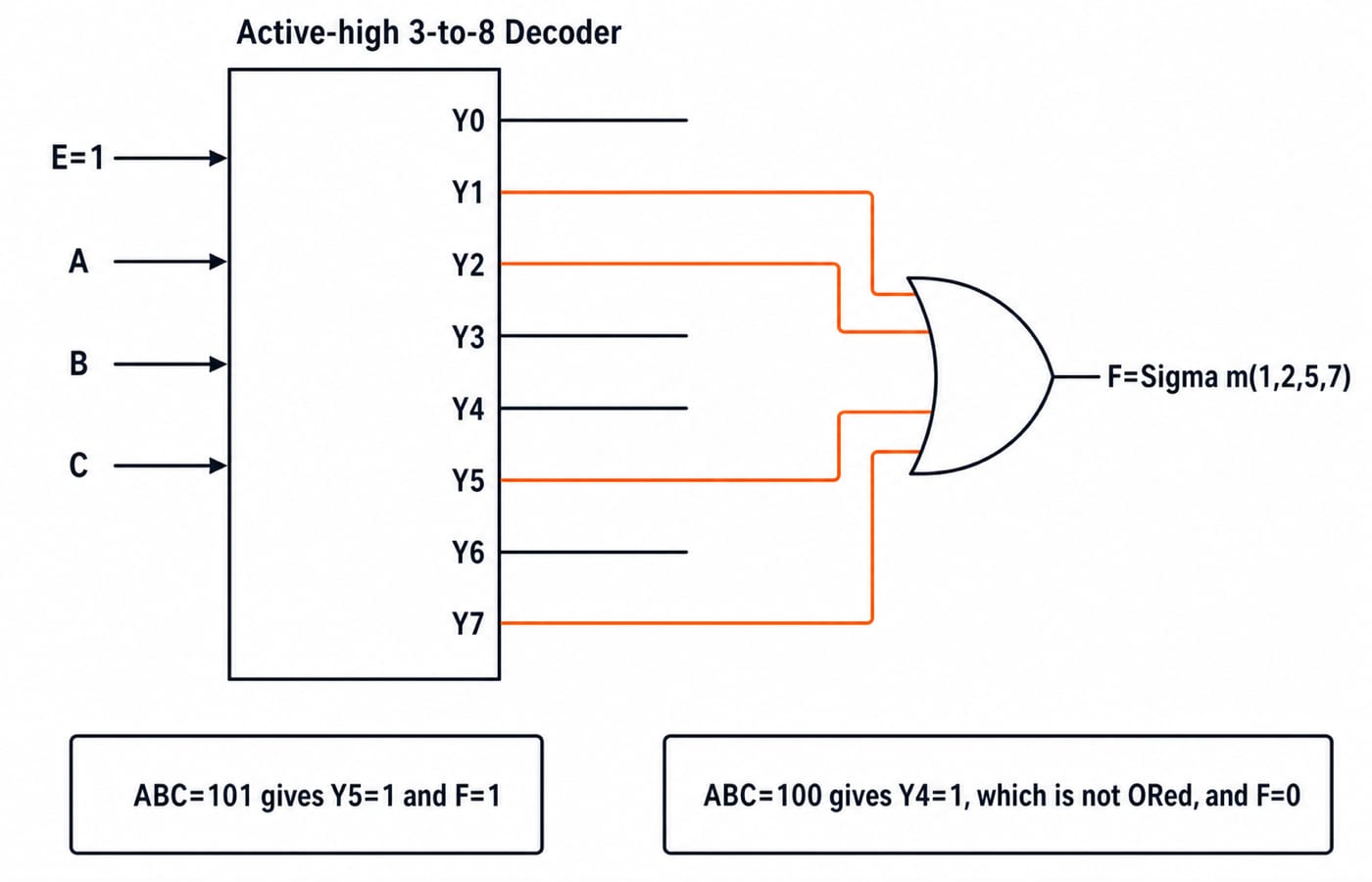
Let F(A,B,C)=Sigma m(1,2,5,7). Its sum of minterms is:
F=A'B'C + A'BC' + AB'C + ABC
Feed A,B,C to a 3-to-8 active-high decoder with E=1, then OR Y1,Y2,Y5,Y7. Thus F=Y1+Y2+Y5+Y7.
At
ABC=101, onlyY5=1, soF=1.At
ABC=010, onlyY2=1, soF=1.At
ABC=100, onlyY4=1. It is not connected to the OR gate, soF=0.At
ABC=111, onlyY7=1, soF=1.
For the DeMUX version, tie D=1, use A,B,C as selects, and OR O1,O2,O5,O7. Tying D=0 forces every output, and therefore F, to constant 0. That is the common connection error.
6. DeMUX, decoder and encoder traps that change the answer
Trap | What goes wrong | Reliable check |
|---|---|---|
Pin count | A DeMUX data pin is counted as another select | A 1-to-8 DeMUX has one data input plus three selects; a 3-to-8 decoder has three code inputs, usually plus enable |
Active level | A selected zero is mistaken for an inactive output | At input |
Multiple encoder inputs | An ordinary encoder produces a misleading code |
|
Zero code |
| Check |
Line number |
| Rebuild the minterm using the declared variable order |
An encoder is not automatically a perfect decoder inverse when priority, enable or active-low conventions differ. For a DeMUX used as a decoder, constant 1 belongs on D; the variables belong on the select lines.
7. How exam-style questions test these combinational blocks
Exam-style questions usually change one condition at a time: the symbol, active level, enable state, input direction, priority rule or number of cascade stages. Solve from the declared pins and equations before using a memorised block shape.
Five answer-first checks are worth doing from memory:
A 1-to-64 DeMUX needs
log2(64)=6select lines because2^6=64.A 5-to-32 decoder has
2^5=32outputs.An active-high 3-to-8 decoder with
E=1and input110selectsY6.An 8-to-3 highest-priority encoder with
I6=I3=1outputs110.F=Sigma m(1,2,5,7)requires lines1,2,5,7to feed the OR gate after decoding.
For a cascade check, build a 4-to-16 decoder from enabled 2-to-4 decoders. One first-stage device decodes A3A2; its outputs enable four second-stage devices sharing A1A0. Total devices are 1+4=5. At A3A2A1A0=1011, A3A2=10 enables branch 2. Then A1A0=11 selects local output 3, giving global Y(4x2+3)=Y11.
For question-bank practice after these worked traces, use Combinational Circuits MCQs: 12 Solved MUX and Adders. The GATE Test Series adds a broader timed check.
8. DeMUX, decoder and encoder: the short version and next step
Choose a decoder to turn an n-bit code into one active line, a DeMUX to steer data with n selects, and an encoder to turn one valid active line into an n-bit code. Always check the active level and enable or valid convention.
Test the shared pattern from memory: explain why 101 selects decoder line 5, why D=1,S=101 raises only DeMUX output 5, and why only I5=1 returns 101,V=1. Then redraw F=Sigma m(1,2,5,7) with four decoder outputs feeding one OR gate.
For a sequenced Digital Logic path, continue with GATE Guidance by Sanchit Sir.
Keep learning
Functional Completeness in Digital Logic: NAND, NOR and Worked Examples
Learn what makes a Boolean operator set complete, how NAND and NOR recover a standard basis, and how to verify a four-gate NAND construction.
Updated 2 Oct 20266 min readDigital Logic
Boolean Function Counts: Formulas, Worked Examples and Exam Traps
Build the master Boolean-function formula from output choices, then learn how common restrictions change the count through combinations, pairing and inclusion-exclusion.
Updated 27 Sep 20266 min readDigital Logic

Analog-Digital Conversion Basics: ADC, DAC, Worked Examples and Exam Patterns
Build ADC and DAC basics from one consistent transfer model, then practise code selection, reconstruction error, flash and SAR conversion, and bit-depth calculations.
Updated 25 Sep 20266 min readDigital Logic

Universal Realization with NAND and NOR Gates: Concepts, Worked Example and Exam Patterns
Learn why NAND and NOR are universal, then implement one three-variable function using four NAND gates and four NOR gates with verified input traces.
Updated 23 Sep 20265 min readDigital Logic