Input Output Organisation in COA: Programmed I/O, Interrupts and DMA, with Worked Examples
See how Data, Status and Control registers support programmed I/O, interrupts and DMA. Then solve a complete cycle-stealing bandwidth calculation.
KnowledgeGate Team
Exam prep & CS education
Updated 9 Aug 20266 min read

Students remember polling, interrupt, DMA and memory-mapped I/O, yet freeze when a numerical asks what the CPU loses. The missing link is why these methods exist. Input output organisation bridges the speed gap between a fast CPU and slow devices, and each transfer mode is a different bargain over who waits: the processor, the device, or a controller acting for both.
Why input output organisation exists: the speed gap
A CPU works in nanoseconds, while disks, keyboards and network devices may respond in microseconds or milliseconds. Waiting for each transfer wastes useful processor cycles.
An I/O module, or interface, bridges the CPU and device through three registers:
The Data register holds the byte or word being transferred.
The Status register reports conditions such as ready, busy or error.
The Control register accepts commands such as start-read or start-write.
Every method in this topic uses these same registers. The three transfer modes differ mainly in who watches the Status register and who moves the data.
The I/O interface and how the CPU addresses a device
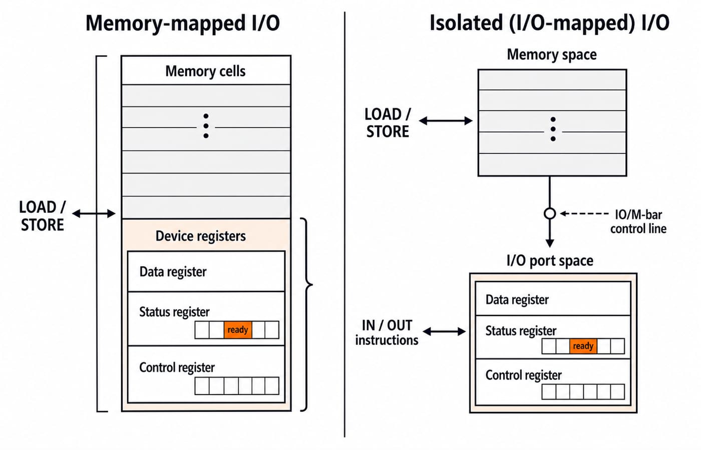
The interface registers need addresses. Systems provide them in two ways.
Scheme | Address space | Instructions | Main trade-off |
|---|---|---|---|
Memory-mapped I/O | Device registers and memory share one address space | Ordinary LOAD and STORE instructions | Simpler programming, but device registers occupy part of the memory address range |
Isolated I/O, also called I/O-mapped or port-mapped I/O | Memory and I/O ports have separate address spaces | Dedicated IN and OUT instructions | The full memory range remains available, but the CPU needs special instructions and control hardware |
In isolated I/O, an IO/M-bar line selects memory or an I/O port. The exam distinction is crisp: memory-mapped I/O uses normal instructions on device registers; isolated I/O uses dedicated IN and OUT instructions in a separate space.
Worked example: what memory-mapped I/O costs the address space
Take a processor with a 16-bit address bus, so it can name 2^16 = 65,536 locations, and an interface block that reserves 1 KB, that is 1,024 addresses, for device registers.
Step 1: Find what memory keeps under memory-mapped I/O.
65,536 - 1,024 = 64,512 addresses = 63 KB
Step 2: Express the device block as a fraction of the space.
1,024 / 65,536 = 1/64 = 0.015625 = 1.5625%
Memory-mapped I/O therefore gives the device block about 1.6 percent of the address space, and addressable memory falls from 64 KB to 63 KB. Under isolated I/O the full 64 KB stays available, because those 1,024 port addresses live in their own space reached by IN and OUT. That is the trade-off in the table above, priced.
Three ways to move data: programmed I/O, interrupts and DMA
Programmed I/O
In programmed I/O, or busy-wait polling, the CPU reads the Status register until ready becomes 1, then moves the data. It suits simple, occasional access, but the CPU does no useful work while polling.
Interrupt-driven I/O
With interrupt-driven I/O, the CPU starts the operation and continues other work. When ready, the device interrupts; the CPU runs an Interrupt Service Routine (ISR), moves the data and resumes. Polling disappears, but the CPU still transfers every byte and pays ISR overhead.
Direct Memory Access
With Direct Memory Access (DMA), a controller moves a block between the device and memory. The CPU sets the starting address, direction and count, then receives one completion interrupt. DMA suits bulk transfers such as disk blocks.
Programmed I/O wastes the CPU. Interrupts free it between bytes. DMA frees it from moving the bytes.
Interrupt-driven I/O and priority among devices
On an interrupt, the CPU finishes its instruction, saves the Program Counter and status, and jumps to the ISR. It later restores state and resumes. Interrupt latency is the delay from the request to the ISR's first useful instruction.
If several devices can interrupt, the system also needs a priority method:
Software polling: the CPU checks devices in a fixed order, which becomes the priority. It is simple but slow.
Daisy chaining: the acknowledge signal passes along a hardware chain. The nearest device receives it first, so position fixes priority.
Vectored interrupts: the device supplies its ISR vector. The CPU reaches the correct handler without polling.
Remember the mechanism: daisy chaining uses physical position, while vectored interrupts remove the search.
DMA modes and a worked cycle-stealing example
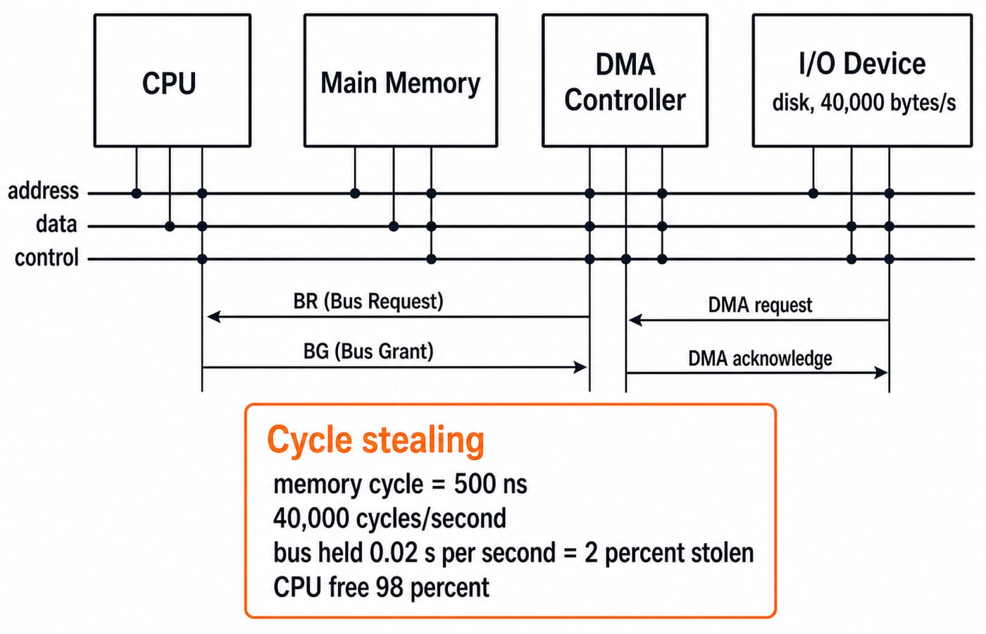
The DMA controller sends a Bus Request (BR). The CPU completes its bus cycle, returns a Bus Grant (BG) and releases the bus. The device and controller use DMA-request and DMA-acknowledge signals.
DMA can then use the bus in three common modes:
Burst or block mode: DMA holds the bus for the whole block. This is fast but stalls CPU bus access.
Cycle stealing: DMA takes one memory cycle, then releases the bus so the CPU can run.
Transparent or hidden mode: DMA transfers only when the CPU does not need the bus, so the running program never stalls.
Consider a disk delivering 40,000 bytes per second. DMA cycle stealing moves 1 byte per 500 ns memory cycle. What fraction of memory cycles does it steal?
Step 1: Find the cycles required each second.
One byte needs one cycle, so:
40,000 bytes/s × 1 cycle/byte = 40,000 cycles/s
Step 2: Find how long DMA holds the bus each second.
40,000 cycles/s × 500 ns/cycle = 20,000,000 ns/s
Since 1 ns = 10^-9 s:
20,000,000 × 10^-9 s = 0.02 s = 20 ms
DMA therefore holds the bus for 0.02 second out of every second.
Step 3: Find the stolen fraction.
0.02 s / 1 s = 0.02 = 2%
DMA steals 2 percent of memory bandwidth, leaving 98 percent for the CPU. Programmed I/O could keep the CPU polling throughout, effectively occupying it 100 percent. That contrast is why DMA exists.
How GATE and interviews test input output organisation
GATE CS uses recurring question shapes: calculate DMA transfer time or stolen bus time, identify priority in a daisy chain, or distinguish memory-mapped from isolated I/O. This post gives you the map; the rate and overhead arithmetic is worked end to end in DMA, Interrupts and Programmed I/O for GATE, which converts a device rate, a bus clock and an ISR cycle cost into stolen-cycle and CPU-fraction percentages.
The official GATE CS syllabus lists Computer Organization and Architecture, including the I/O interface in interrupt and DMA mode, and the syllabus PDF on the current GATE organising institute's website carries the exact wording. Input output organisation also appears regularly in KnowledgeGate's Computer Organization and Architecture question bank, alongside cache, pipelining and addressing modes.
Interviews usually ask why interrupts beat polling, when DMA fits, and what memory-mapped I/O means. Answer each by naming who watches the Status register and who moves the data: the CPU does both while polling, the CPU moves the data but only after the device signals under interrupts, and the controller does both for a whole block under DMA.
For a structured study path, GATE Guidance by Sanchit Sir places input output organisation within the full Computer Organization and Architecture sequence. The GATE CS Exam preparation category connects it to the rest of the syllabus.
The short version and your next step
Input output organisation starts with one problem, the CPU-device speed gap, and offers three increasingly efficient responses:
Programmed I/O makes the CPU poll and wait.
Interrupt-driven I/O lets the CPU work between device events, although it still moves the data.
DMA lets a controller move the data and interrupts the CPU only at completion.
Here, DMA uses 0.02 second of bus time per second, or 2 percent, leaving 98 percent for the CPU, and memory-mapped I/O costs a 16-bit machine 1,024 of its 65,536 addresses, about 1.6 percent. Hand-solve both once and each numerical becomes a short unit conversion.
Then build the neighbouring COA ideas through Cache Memory: Mapping and Hit Ratio and Memory Hierarchy and Virtual Memory. When you want the complete subject in GATE order, continue with the guidance course from the study path above.
Keep learning
Programmed I/O: Polling, CPU Utilisation, Worked Examples and GATE Question Patterns
Follow one programmed-input transfer from control write to data read, then calculate how many polls one word costs and what a longer poll period buys.
Updated 7 Oct 20266 min readComputer Organization & Architecture
Multiprocessor Fundamentals: Architecture, Speedup and Worked Examples
Build a clear model of multiprocessor systems, then use it to calculate speedup and efficiency, trace a coherent write, and diagnose a lost update.
Updated 2 Oct 20265 min readComputer Organization & Architecture

Multiprocessor Classification: Flynn Taxonomy, Memory Models and Exam-Style Worked Examples
Learn how to choose the right multiprocessor classification axis, then solve a four-lane SIMD trace and a NUMA average-access-time problem step by step.
Updated 27 Sep 20266 min readComputer Organization & Architecture
Interrupt-Driven I/O Explained: CPU Handshake, Worked Timing Example and GATE Traps
Trace an interrupt from device request to return-from-interrupt, then compare polling, per-event interrupts, and DMA through worked timing examples.
Updated 25 Sep 20267 min readComputer Organization & Architecture