Addressing modes and instruction formats in computer architecture explained
Addressing modes and instruction formats explained: immediate, direct, indirect, indexed and PC-relative effective addresses, and 0/1/2/3-address machines.
KnowledgeGate Team
Exam prep & CS education
Updated 16 Jul 20267 min read340 views
An instruction has to say two things: what operation to perform, and where its operands live. Addressing modes are the rules for that second part, the different ways an instruction names the location of its data. Instruction formats are how those rules get packed into a fixed number of bits. Get these two ideas straight and a large, reliably tested slice of computer organisation becomes arithmetic you can do on paper.
Almost everything asked on this topic reduces to three calculations: an effective address, a bit budget split between opcode and address fields, and an instruction count for one expression. Each has a formula you can apply cold, and none of them needs more than powers of two.
Related reading: array address calculations and computer organisation practice.
Addressing modes: computing the effective address
The effective address is the actual memory address from which the CPU finally fetches the operand. Every addressing mode is just a different formula for producing it.
Immediate. The operand is inside the instruction itself.
MOV R1, #5loads the constant 5. No memory reference and no effective address to compute; the value is fixed at assembly time.Register. The operand is in a register.
ADD R1, R2uses the contents of R2 directly. No memory access for the operand, which is why register operations are the quickest.Direct (absolute). The instruction holds the operand's memory address. Effective address = the address field. One memory reference to fetch the operand.
Indirect. The instruction holds the address of a location that itself holds the operand's address. Effective address = contents of the address field. Two memory references, one for the pointer and one for the operand.
Register indirect. A register holds the operand's address. Effective address = contents of the register. One memory reference for the operand, none to find its address.
Indexed. Effective address = base address in the instruction + contents of an index register. Ideal for stepping through an array: keep the array's start in the address field and the element number in the index register.
Base-register relative. Effective address = contents of a base register + a displacement. The mirror image of indexed, used for relocatable code and record fields.
PC-relative. Effective address = contents of the program counter + a signed offset. This is how branches are usually encoded, since most jumps are to nearby instructions and a short signed offset suffices.
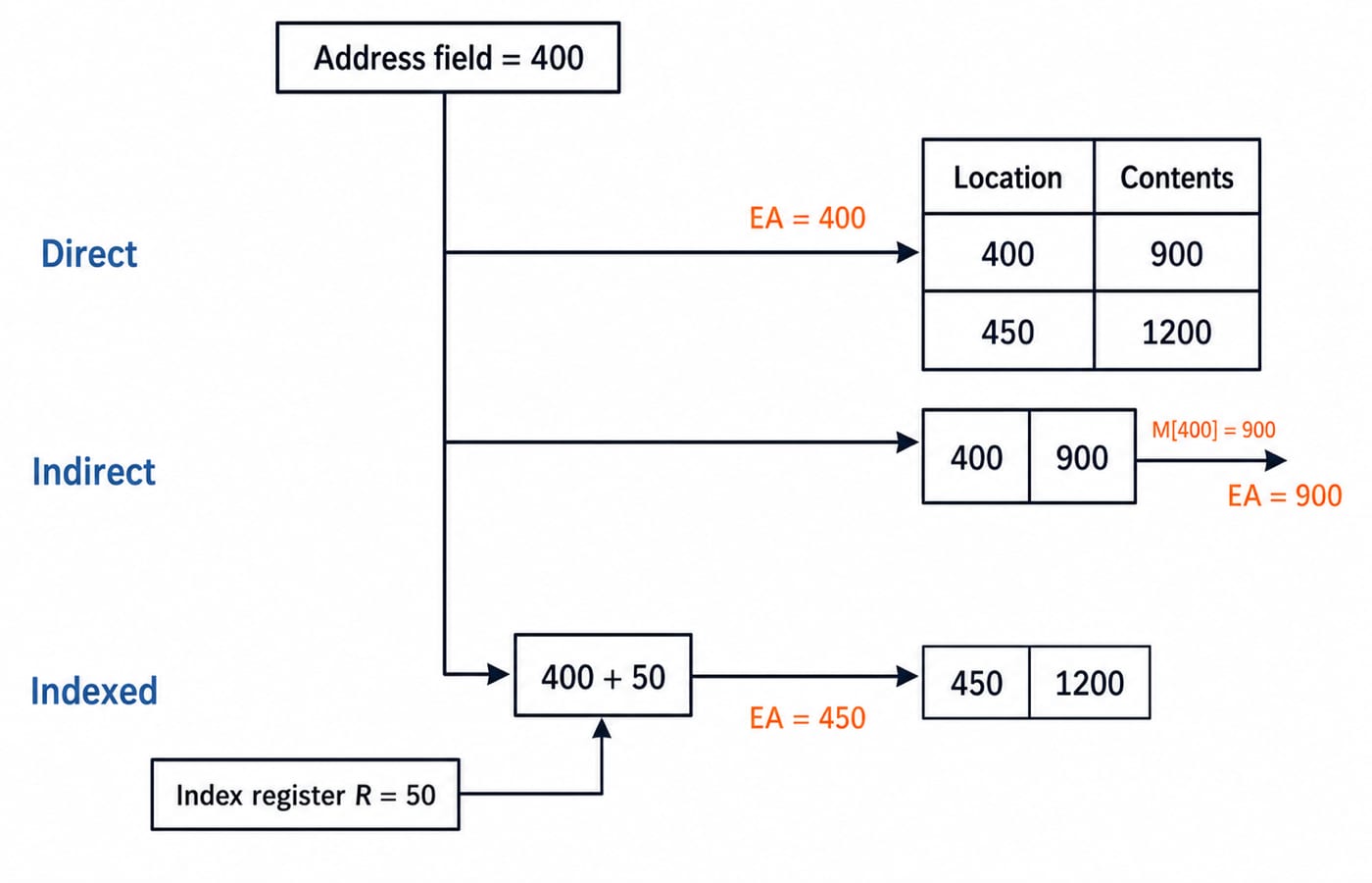
A quick worked check. The address field holds 400, index register R holds 50, memory location 400 holds 900, and location 450 holds 1200.
Direct: effective address 400, operand fetched = 900.
Indirect: effective address = contents of 400 = 900, operand fetched from 900.
Indexed: effective address = 400 + 50 = 450, operand fetched = 1200.
Three modes, three different operands, from the same address field. That is the heart of most exam questions on the topic.
Instruction formats: fields and opcode encoding
An instruction is a fixed pattern of bits split into fields. The two that always appear are the opcode, which selects the operation, and zero or more operand or address fields, which name the data. Many architectures add a mode field telling the hardware which addressing mode to apply to each operand.
The opcode length decides how many distinct operations the machine can encode: n opcode bits give 2 to the power n instructions. There is a direct tension: more bits on the opcode means more operations but fewer bits for the address field. Take a 16-bit instruction with a single address field. A 4-bit opcode buys 16 operations and leaves 12 address bits, naming 4,096 locations; a 5-bit opcode buys 32 operations but reaches only 2,048. Every opcode bit doubles the instruction set and halves the memory you can name directly.
Two encoding styles resolve that tension.
Fixed-length encoding gives every instruction the same width. Decoding is simple and pipelining is easier, the RISC approach. The cost is wasted bits in instructions that need no full address.
Variable-length encoding lets each instruction be as long as it needs, packing code densely (the CISC approach) at the price of harder decoding.
Expanding opcodes are the middle path: short opcodes for instructions that need long address fields, longer opcodes for instructions that need few or no addresses. The bit budget is the same, spent where each instruction needs it.
Expanding opcodes: counting the instruction set
Work it on a 16-bit instruction whose addresses are 4 bits wide, reserving one code at each level as the escape into the next.
Three-address: a 4-bit opcode plus three 4-bit addresses fills the word. Use 15 of the 16 codes and reserve
1111as the escape. 15 instructions.Two-address: the escape plus the next 4 bits gives an 8-bit opcode, and two addresses fill the rest. Again 15 usable, 1 escaping. 15 instructions.
One-address: a 12-bit opcode and one 4-bit address field. 15 usable, 1 escaping. 15 instructions.
Zero-address: the last escape plus 4 more bits gives a 16-bit opcode with no room for an address. All 16 are usable. 16 instructions.
That is 15 + 15 + 15 + 16 = 61 instructions inside a fixed 16-bit word, against the 16 a flat 4-bit opcode allows. The reserved escape codes are what you pay for it.
0, 1, 2 and 3-address machines
How many operands an instruction names is an architectural choice with real consequences for code length and memory references. Machines are classified by addresses per instruction.
3-address: each instruction names two source operands and a destination.
ADD R1, R2, R3means R1 = R2 + R3. Programs are short but each instruction is wide.2-address: one operand doubles as source and destination.
ADD R1, R2means R1 = R1 + R2. The old R1 is overwritten.1-address: a single implied register, the accumulator, is one operand and the destination of every operation.
ADD Bmeans AC = AC + B.0-address: operands are taken implicitly from the top of a stack.
ADDpops the top two values, adds them, and pushes the result. This is a stack machine.
One expression, four machines
Evaluate X = (A + B) * (C + D) on each and count the instructions.
Machine | Program | Instructions |
|---|---|---|
3-address | ADD T1, A, B ; ADD T2, C, D ; MUL X, T1, T2 | 3 |
2-address | MOV T1, A ; ADD T1, B ; MOV T2, C ; ADD T2, D ; MUL T1, T2 ; MOV X, T1 | 6 |
1-address | LOAD A ; ADD B ; STORE T1 ; LOAD C ; ADD D ; MUL T1 ; STORE X | 7 |
0-address | PUSH A ; PUSH B ; ADD ; PUSH C ; PUSH D ; ADD ; MUL ; POP X | 8 |
Read the trade-off straight off the table. The 3-address machine says the most per instruction, so its program is shortest and its instructions widest. The 0-address machine has tiny instructions carrying no address at all, but needs the most of them, and its operand ordering is exactly a postfix (reverse Polish) evaluation. The accumulator machine sits in between. Fewer addresses per instruction means more instructions.
How addressing modes and instruction formats are tested
GATE CS treats this as core computer organisation. The most common question hands you an addressing mode with register or memory contents and asks for the effective address or the final operand, exactly the direct-versus-indirect-versus-indexed computation above. A second staple asks you to count memory references for a mode, or to count how many instructions an expanding-opcode format allows, the 61-instruction arithmetic worked above. The 0, 1, 2, 3-address classification appears as "how many instructions to evaluate this expression".
Placement and other tests keep it conceptual: name the modes, explain PC-relative addressing for branches, or contrast RISC fixed-length with CISC variable-length encoding.
Once you are fluent here, the natural next topic is how these decoded instructions flow through the hardware: pipelining in computer architecture picks up where instruction formats leave off, with fixed-length encoding letting the fetch-decode-execute stages overlap cleanly.
The short version
An addressing mode is a formula for the effective address: immediate and register touch no memory, direct and register-indirect take one reference, indirect takes two, while indexed and PC-relative add a register to a field. Instruction formats split bits between opcode and address. The 0-to-3-address classification trades instruction width against instruction count, felt best by hand-coding one expression four ways.
Drill the effective-address and expression-evaluation numericals, then work the full topic with solved problems in the Computer Architecture learn module.
For a GATE-depth sequence that places computer organisation alongside the rest of the syllabus, GATE Guidance by Sanchit Sir is built for it; placement aspirants can start from the CS Fundamentals category.
Compute one effective address in every mode and hand-code one expression on all four machine classes. Do that and this topic converts into marks.
Keep learning
RISC vs CISC Architecture: Control Units, CPI Worked Example and Exam Patterns
Understand what RISC and CISC actually classify, then compare code size and performance with step-by-step instruction and CPU-time examples.
Updated 26 Oct 20266 min readComputer Organization & Architecture
Memory Chip Configuration: Chip Count, Address Lines and Two Worked Designs
Learn to separate depth expansion from width expansion, wire chip banks, derive address pins and check hexadecimal ranges with two complete examples.
Updated 25 Oct 20265 min readComputer Organization & Architecture

Pipelining Basics in Computer Architecture: Clock Cycle, Speedup and Hazard Worked Examples
Learn how to calculate a pipeline clock, fill and drain time, finite-batch speedup, latency, throughput, and the cost of a load-use stall.
Updated 23 Oct 20266 min readComputer Organization & Architecture

Data Manipulation Micro-Operations in COA: Arithmetic, Logic and Shift Operations Worked Step by Step
Learn a fixed-width method for tracing arithmetic, logic, and shift micro-operations. Every example tracks register values, result bits, carry, and overflow.
Updated 19 Oct 20265 min readComputer Organization & Architecture