DMA is often memorised as “data moves without the CPU”. That hides who owns the bus, what the CPU still does, and how the address and count change. For a 6 KiB device-to-memory block, the trace fixes the word count, last address, bus time and occupancy. See GATE CS Exam Preparation for wider study.
What DMA changes in an I/O transfer
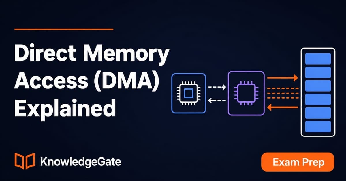
Programmed I/O makes the CPU poll and move each data unit. Interrupt-driven I/O reduces polling, but the CPU normally moves each ready unit or small buffer. With DMA, the CPU sets up a block, the controller becomes bus master, and an interrupt usually reports completion or error.
DMA removes the CPU from the copy loop, not the whole operation. The CPU still supplies direction, starting address, count and controls. Arbitration and completion handling remain.
Method | Who moves each data unit? | CPU notification | Best fit | Main cost |
|---|---|---|---|---|
Programmed I/O | CPU | Polling | Tiny or infrequent transfers | Repeated CPU work |
Interrupt-driven I/O | CPU in the service path | Interrupts as data becomes ready | Infrequent units or small buffers | Interrupt and copy overhead |
DMA | DMA controller | Usually completion or error interrupt | Blocks that amortise setup | Setup and bus contention |
For where DMA sits in the whole I/O picture (the three interface registers, memory-mapped versus isolated addressing, and interrupt priority), start from Input Output Organisation in COA. This post never leaves the controller.
For a side-by-side CPU-occupancy comparison of programmed I/O, interrupts and DMA, use Computer Interfaces in COA. For the peripheral side, including direction, natural transfer unit and FIFO sizing, use Input and Output Devices in COA. A DMA-only trace instead follows controller state, bus ownership, address progression and mode-specific timing.
DMA controller registers and transfer sequence
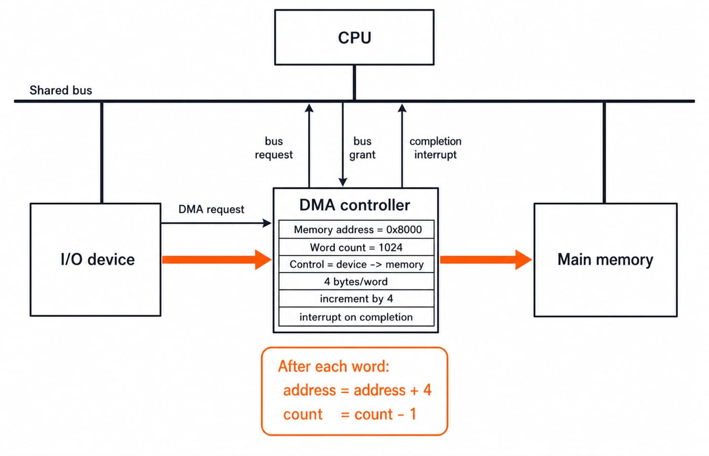
A logical controller needs memory-address, transfer-count and control or status registers plus a device data path. Names vary. Counts may represent bytes, words or transactions. Here, the count register holds 4-byte words.
The CPU writes address = 0x8000, count = 1536 words, direction = device to memory, word size = 4 bytes, increment = 4, and completion interrupt = enabled. The device raises a DMA request. The controller requests the bus, the current cycle finishes, and an arbiter grants it.
DMA transfers the data. After each word, address rises by 4 and count falls by 1. Terminal count or error changes status, releases the bus and interrupts the CPU. HOLD and HLDA are architecture-specific examples. Addressing Modes and Instruction Formats concerns instruction operands, while DMA generates later addresses autonomously.
Worked DMA example: move 6 KiB into memory
Assume 6 KiB = 6144 bytes, one 32-bit = 4-byte word per transfer, 50 ns of occupied bus time per transfer, and destination byte address 0x8000. The count register holds words. These values define this example, not universal hardware.
Word count = 6144 / 4 = 1536. The first word fills 0x8000 through 0x8003. Word i begins at 0x8000 + 4i, so word 1535 begins at 0x8000 + 6140 = 0x97FC and ends at 0x97FF. The final update leaves next address 0x9800 and count 0.
Bus work = 1536 x 50 ns = 76,800 ns = 76.8 microseconds. Its continuous bus limit is 6144 bytes / 76.8 microseconds = 80,000,000 bytes/s = 80 MB/s, in decimal MB/s. This excludes setup, device waits, arbitration gaps, memory waits and interrupt service.
Burst, cycle-stealing and transparent DMA
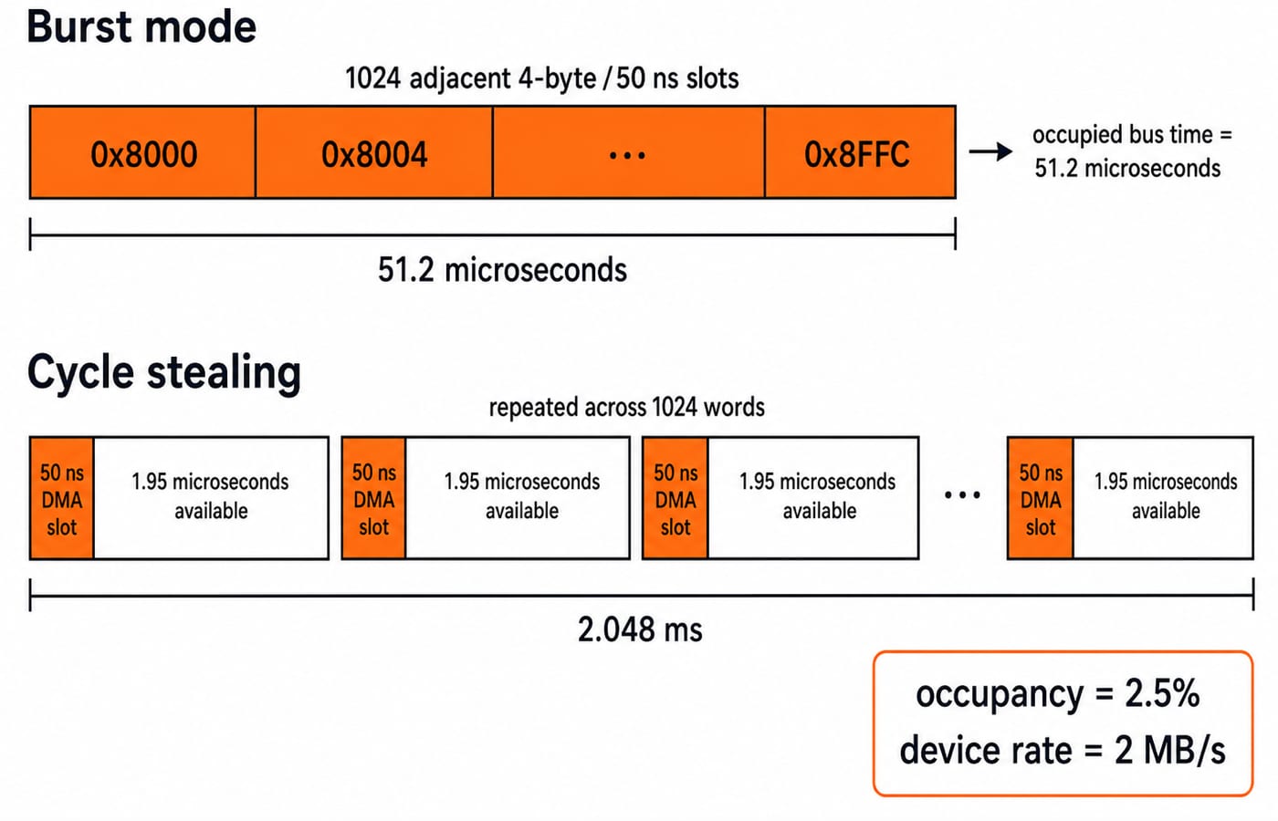
In burst mode, one grant covers 1536 adjacent transfers and 76.8 microseconds. A CPU may do internal work that avoids this bus, but it cannot use the shared memory bus during the burst.
For cycle stealing, suppose one 4-byte word is ready every 2 microseconds. These values define this example, not universal hardware. Block interval = 1536 x 2 microseconds = 3072 microseconds = 3.072 ms. Bus time stays 76.8 microseconds, so occupancy = 76.8 / 3072 = 0.025 = 2.5%. Device rate = 4 bytes / 2 microseconds = 2 MB/s. The CPU loses 2.5% of this bus's time, not 2.5% of total performance.
Transparent DMA transfers only while the bus is otherwise idle. It reduces visible contention, but completion depends on idle opportunities.
Mode | Grant duration | CPU bus interruption | Predictability and worked value |
|---|---|---|---|
Burst | Whole block | One continuous interval | Predictable |
Cycle stealing | One transfer at a time | Repeated |
|
Transparent | Idle periods only | Low visible contention | Completion varies with bus idleness |
Read DMA performance numbers carefully
Three limits matter: device rate, shared-bus width and cycle time, and memory or controller latency. The burst bus supports 80 MB/s, but cycle stealing is device-limited to 2 MB/s. DMA cannot exceed the slowest limit.
Assume for teaching that setup plus completion costs 5 microseconds. Burst total = 5 + 76.8 = 81.8 microseconds; setup share = 5 / 81.8 = 6.1%. One 4-byte transfer would pay that setup for 50 ns of bus work, so DMA can waste effort on tiny transfers. This value is not a hardware constant.
DMA does not guarantee cache consistency. If the CPU retains stale cached data after a device writes memory, coherent DMA, invalidation or synchronisation may be needed before reading.
Common DMA traps and corrections
Trap | What goes wrong | Correction |
|---|---|---|
“DMA uses no CPU” | Ignores setup and completion | CPU configures and completes it |
Count is 6144 | Treats bytes as words | This register holds |
Last address is | Confuses last and next | Last byte |
| Converts nanoseconds incorrectly |
|
| Confuses bytes and bits |
|
Occupancy equals CPU slowdown | Overgeneralises |
|
Burst mode need not stop all CPU execution. Transparent DMA trades lower visible contention for uncertain idle slots. Check 1536 x 4 = 6144 bytes, last byte 0x97FF, next address 0x9800, count 0.
How GATE tests DMA and cycle stealing
The official GATE 2026 Computer Science syllabus listed “I/O interface (interrupt and DMA mode)” under Computer Organization and Architecture. That establishes past-cycle scope only. Check the official site for your cycle, without assuming fixed marks or frequency.
Prompts may ask for the bus sequence, address or count updates, mode comparisons, or data rate from stolen cycles. Keep units on every line.
If the question gives you a bus clock rather than a per-transfer bus time, the accounting unit changes; DMA, Interrupts and Programmed I/O for GATE works that form, dividing a required cycle rate by an available bus-cycle rate.
Official GATE 2021 CS Set 2, Q20 used a 2 MHz processor, 0.5% stolen cycles and one 8-bit character per stolen cycle. Thus stolen cycles/s = 2,000,000 x 0.005 = 10,000; data rate = 10,000 x 8 = 80,000 bits/s. This is a past-paper example, not a forecast.
A second GATE-style check: 3 KiB = 3072 bytes on a 32-bit = 4-byte bus needs 3072 / 4 = 768 transfers. At 125 ns each, time = 96 microseconds and rate = 32 MB/s. From 0x2000, the last word begins at 0x2BFC and ends at 0x2BFF; next address is 0x2C00. These values define this check, not universal hardware.
DMA: the short version and next step
Solve in order: define the count unit; divide bytes by transfer size; trace last and next addresses; multiply transfers by bus time; separate occupancy from CPU performance. Here, 6144 bytes -> 1536 words -> 0x8000 through 0x97FF -> 76.8 microseconds.
Redraw the sequence, then recover why the last word starts at 0x97FC, next address is 0x9800, and 50 ns every 2 microseconds means 2.5%. Repeat the arithmetic if these values do not return cleanly.
For wider study, GATE Guidance by Sanchit Sir provides a structured GATE CS path, while Zero to Hero Complete CS Course covers broader fundamentals.