Memorising LOAD, ADD, and JUMP does not solve a trace where instructions change registers, flags, or the next PC. Instruction effects include changes to registers, flags, memory, branches, the PC, and I/O, and each type corresponds to a datapath action. Category and flag conventions vary, so these rules belong to a declared toy ISA.
Instruction types in computer organization: classify by state change
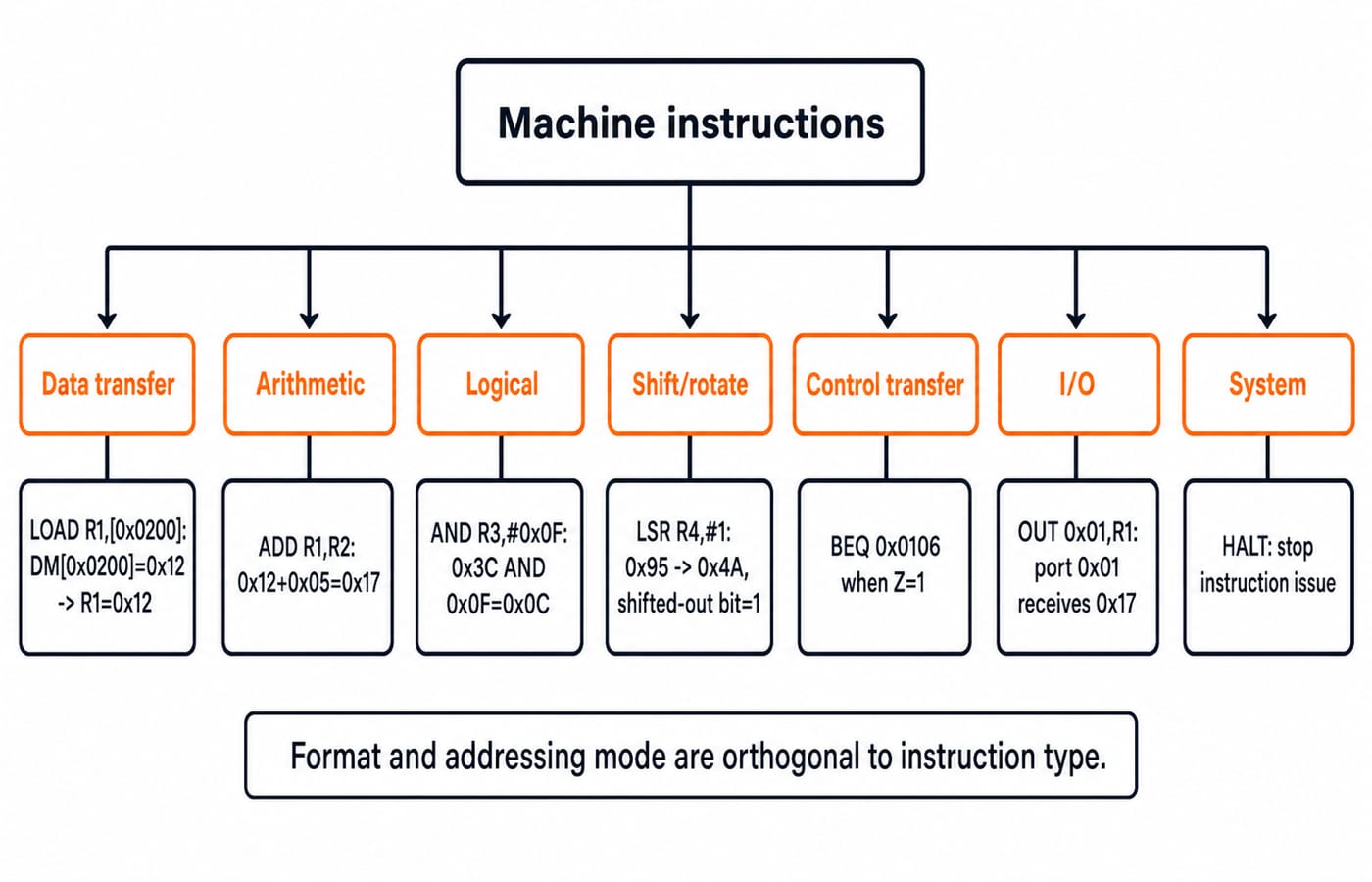
A machine instruction encodes an operation. Its opcode selects the control action; operand fields identify values, registers, locations, or targets. Architectural effects give seven groups: data transfer, arithmetic, logical, shift and rotate, control transfer, input/output, and system control. Some books combine arithmetic, logic, and shifts as data processing. Only the name differs.
Type | Architectural state changed | Typical opcodes | Toy-ISA example |
|---|---|---|---|
Data transfer | Register or memory value |
|
|
Arithmetic | Value, possibly flags |
|
|
Logical | Value, possibly flags |
|
|
Shift/rotate | Value, possibly shifted bit or flags |
|
|
Control transfer | Program counter |
|
|
I/O | Port or register |
|
|
System control | Execution state |
|
|
Instruction type asks what occurs. Format describes field layout. Addressing mode describes how an operand or effective address is obtained. Thus ADD R1,R2 and ADD R1,[R2] are both arithmetic, with different source addressing modes. Use Computer Instruction Explained: Format, Instruction Cycle and a 16-Bit Worked Example for 16-bit field decoding, signed displacement arithmetic, and one LOAD from fetch to write-back. For mixed opcodes, classify by the register, flag, memory, PC, or I/O state written.
Data-transfer and data-processing instructions: separate values and flags
Transfer instructions copy bits between locations. If DM[0x0200]=0x12, LOAD R1,[0x0200] makes R1=0x12 while memory stays 0x12; STORE [0x0202],R1 later copies 0x17 to memory. Moves, loads, stores, pushes, and pops qualify, but memory-to-memory legality depends on the ISA.
Three calculations establish the processing rules:
Arithmetic:
0x12 + 0x05 = 0x17. The 8-bit result is non-zero, with no carry.Logical:
0x3C AND 0x0F = 0x0C, since00111100 AND 00001111 = 00001100.Shift: logical right shift gives
0x95 (10010101) -> 0x4A (01001010), shifted-out bit1. Arithmetic right shift preserves the leading one, giving0xCA (11001010).
Here ADD updates zero flag Z and carry flag C; CMP subtracts to update Z without writing a register; LOAD, STORE, and OUT leave both unchanged. Use CPU Organization Basics: Registers, Instruction Cycle and Worked Examples to trace MAR, MDR, IR, and accumulator transfers. When classifying an instruction type, record only architectural register, flag, memory, PC, and I/O writes.
Control-transfer, I/O, and system instructions: track the next PC
The toy CPU uses fixed one-word instructions and a word-addressed PC that advances by one. A jump replaces that PC; BEQ does so only when Z=1. CALL preserves a return address, and RETURN restores it. Real ISAs differ.
OUT 0x01,R1 copies the low 8 bits of R1 to port 0x01; IN moves a port value into a register; HALT stops instruction issue. Some processors use memory-mapped I/O. Control selects memory access, an ALU function, writeback, a branch target, I/O, or halt sequencing.
Instruction types worked example: trace every state
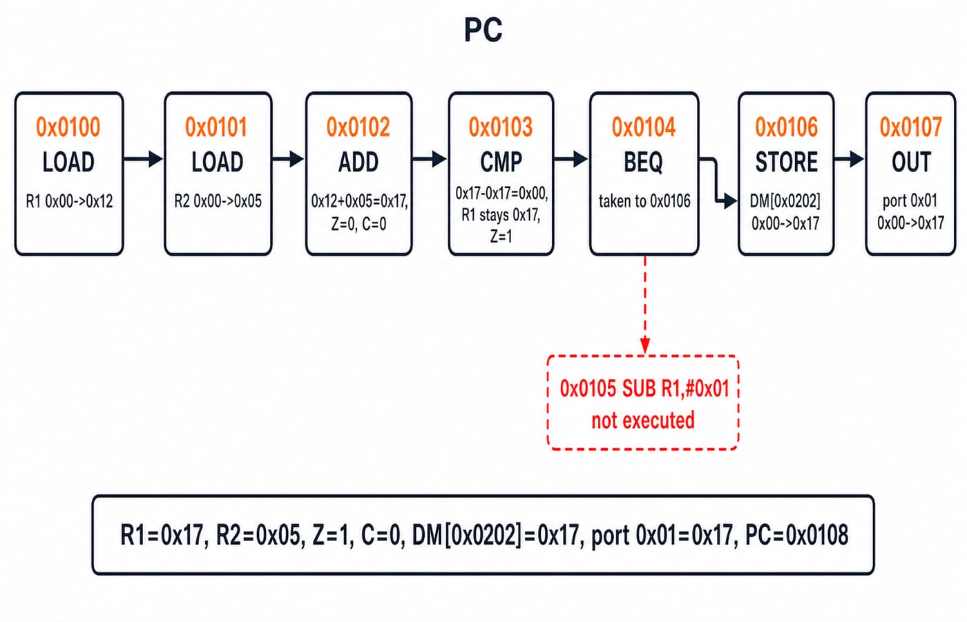
The model has 8-bit R1 and R2, flags Z and C, 16-bit word-addressed IM, 8-bit DM, and one-word instructions. Initially, PC=0x0100, both registers are 0x00, Z=C=0, DM[0x0200]=0x12, DM[0x0201]=0x05, DM[0x0202]=0x00, and port 0x01=0x00. Fall-through adds 1.
0x0100  LOAD  R1,[0x0200]
0x0101  LOAD  R2,[0x0201]
0x0102  ADD   R1,R2
0x0103  CMP   R1,#0x17
0x0104  BEQ   0x0106
0x0105  SUB   R1,#0x01
0x0106  STORE [0x0202],R1
0x0107  OUT   0x01,R1
Step | PC before | Instruction | State change | PC after |
|---|---|---|---|---|
1 |
|
|
|
|
2 |
|
|
|
|
3 |
|
|
|
|
4 |
|
|
|
|
5 |
|
| Taken because |
|
6 |
|
|
|
|
7 |
|
| Port |
|
Final state: R1=0x17, R2=0x05, Z=1, C=0, DM[0x0202]=0x17, port 0x01=0x17, and PC=0x0108.
Instruction types and control-unit design: opcodes to micro-operations
Abstract fetch is MAR <- PC; IR <- IM[MAR]; PC <- PC + 1; decode IR. Execute depends on type:
LOAD:MAR <- 0x0200,MDR <- DM[MAR]=0x12,R1 <- MDR.ADD:ALUOut <- 0x12+0x05=0x17,R1 <- 0x17,Z <- 0,C <- 0.CMP:ALUOut <- 0x17-0x17=0x00,Z <- 1, with register write disabled.BEQ: fetch makesPC=0x0105; becauseZ=1, execute performsPC <- 0x0106.
Opcode | Memory action | ALU action | Register write | Flag write | PC override | I/O action |
|---|---|---|---|---|---|---|
| Read data | Pass value | Yes | No | No | No |
| None | Add | Yes |
| No | No |
| None | Subtract | No |
| No | No |
| None | Condition test | No | No | If true | No |
| Write data | Pass address/value | No | No | No | No |
| None | Pass value | No | No | No | Port write |
Hardwired and microprogrammed control can realise these actions differently, but must produce the same architectural changes. Use Control Unit Design in COA: Hardwired vs Microprogrammed, with Worked Examples for timing tables, Boolean signal equations, and control-memory sizing; use architectural writes, not implementation style, to classify the instruction type.
Instruction-type traps: name the destination state
ADD R1,[R2] is arithmetic despite reading memory. CMP is data processing although its visible result is flags. A mnemonic alone cannot establish operand legality or flag behaviour. Ask which destination state is written.
Do not replace R1 with zero after CMP, because its 0x00 result is discarded. Do not execute SUB at 0x0105, because taken BEQ sends the PC to 0x0106. Do not confuse logical shift 0x95 -> 0x4A with arithmetic shift 0x95 -> 0xCA. Keep scratch columns for register, flag, memory, and PC writes. MOV, LOAD, arithmetic, and shifts have no universal flag rules, so use the stated ISA.
GATE instruction-type questions: classification, traces, and signals
Four useful problem forms are classification by changed state, program tracing, control-action selection, and separating type from format or addressing mode. Use this method:
Write the pre-state.
Decode the operation type.
Apply only the declared writes.
Compute the next PC last.
A correct trace explains why CMP leaves R1=0x17 and sets Z=1, why 0x0105 is skipped, and why memory and port end at 0x17. For wider study, use GATE CS Exam Preparation.
Instruction types in computer organization: the short version and next step
Transfer relocates bits. Arithmetic, logical, and shift instructions transform them. Compare may update only flags, control transfer chooses the next PC, I/O changes interface state, and system instructions control execution. Here R1=0x17, Z=1, branch taken, DM[0x0202]=0x17, and port 0x01=0x17.
Now change only DM[0x0201] from 0x05 to 0x04. ADD gives R1=0x16; CMP R1,#0x17 gives Z=0; BEQ falls through; SUB gives R1=0x15; then memory and port both finish at 0x15. Reproduce that trace without looking back.
For a structured next step across Computer Organization and wider GATE CS preparation, continue with GATE Guidance by Sanchit Sir.