

Computer Hardware and Software Explained: COA Basics with Worked Examples
See how software instructions become hardware actions. Trace an addition through registers and memory, then calculate address width and a complete memory map.
KnowledgeGate Team
Exam prep & CS education
Updated 15 Nov 20266 min read
Memorising CPU, RAM, operating system and compiler definitions does not show how a software statement becomes a hardware operation. Confusion appears when a question asks whether firmware is hardware or software, which component adds, or how instructions and data move through memory and registers. For c = a + b with a = 13 and b = 6, software requests addition, the processor executes it, and an address-width and memory-map calculation shows where the values reside. Computer Organization and Architecture Basics surveys data representation, performance, cache, I/O and pipelines. The calculation below instead follows one arithmetic statement across the software-hardware boundary.
Hardware and software are two layers of one computer system
A computer system is hardware executing software instructions on data. Hardware means physical electronic or electromechanical components; software means programs directing them; data means encoded input and state.
A user enters 13 and 6; an application requests addition; the processor computes 19; memory holds values; storage can retain the program or result. Software specifies; hardware performs.
Architecture covers programmer-visible instructions, registers, data types and addressing modes. Organization covers implementation through signals, buses, memory technology, caches and datapaths.
"Hardware is what you can touch" is weak. Physical implementation is decisive. A program stored in RAM or on an SSD remains software.
Hardware blocks and the exact job of each one
Component | Role | Example state or action |
|---|---|---|
CPU | Control unit coordinates, ALU calculates, registers hold state |
|
Main memory | Supplies active content |
|
Secondary storage | Retains content | Executable on SSD |
Input/output | Accepts or presents data | Keyboard, display |
I/O controller | Coordinates device transfer | Ready signal |
Bus | Carries address, data, control | Memory read |
PC contains the next instruction address; IR holds the current instruction; R1-R3 hold operands or results. MAR selects a location; MDR carries content.
Address lines select, data lines carry, and control lines request read or write. Address and data buses can differ in width. RAM is volatile active memory; SSD is persistent storage. Both are hardware.
Application software, system software and firmware form a path to the CPU
Application software performs user tasks. System software includes the operating system, drivers and translators. Firmware is non-volatile software that initializes or controls a device. Types of Software Explained compares the full system, application, programming and utility taxonomy. The compiler-loader-OS chain below instead follows translation, loading and execution into CPU activity.
For a compiled program, the path is:
Compiler or assembler translates source into machine instructions.
Loader puts executable code and data in memory.
Operating system schedules the process and supplies services.
CPU fetches, decodes and executes.
An interpreter is an alternative. Compiler translates, loader places, OS manages resources, control unit coordinates, and ALU calculates.
Assume byte-addressable memory, 8-bit operands, 12-bit addresses and fixed 4-byte instructions. The illustrative encoding is not the encoding of a named real ISA.
Worked example: trace c = a + b from software to hardware
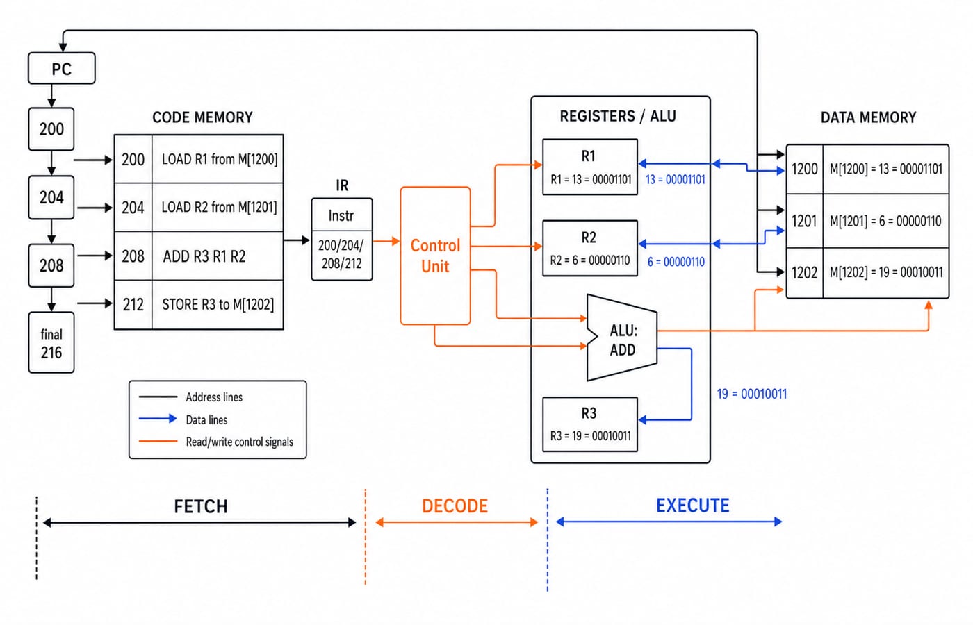
CPU Organization Basics traces every MAR/MDR transfer inside an accumulator CPU. The trace below begins at source-level c = a + b, crosses the compiler-loader-OS boundary, and then uses a shorter three-register path. Initially, a = 13, b = 6, c = 0; M[1200] = 13 (00001101), M[1201] = 6 (00000110), M[1202] = 0; PC is 200; R1-R3 are 0.
Byte address | Toy instruction |
|---|---|
200 |
|
204 |
|
208 |
|
212 |
|
For each fetch, copy PC to MAR, read through MDR into IR, decode, then advance PC by 4. Fetch and operand access are distinct although both use memory here.
At
200, loadM[1200]intoR1:R1 = 13,PC = 204.At
204, loadM[1201]intoR2:R2 = 6,PC = 208.At
208, the ALU computes00001101 + 00000110 = 00010011:R3 = 19,PC = 212.At
212, the control unit requests a write:M[1202] = 19,PC = 216.
The instruction stream is software; PC, IR, registers, ALU, signals, memory and buses are hardware realizing its semantics. Result: c = 19.
Worked example: calculate address width and map memory
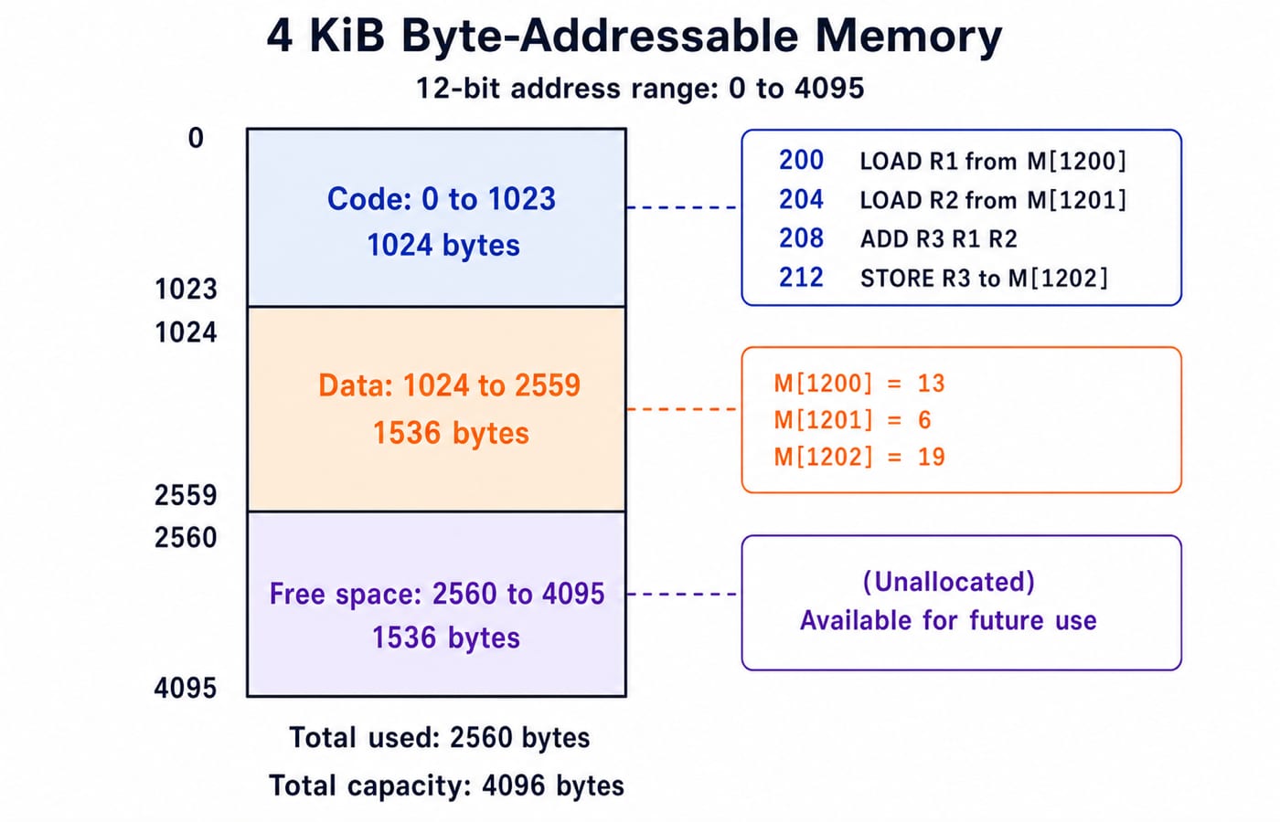
For 4 KiB of byte-addressable memory:
4 KiB = 4 x 1024 = 4096 bytes = 2^12 locations.
It needs 12 address bits, with decimal addresses 0 through 4095.
A program of 256 fixed 4-byte instructions occupies 256 x 4 = 1024 bytes = 1 KiB. At 0-1023, it contains the instruction sequence beginning at 200.
Data of 1.5 KiB uses 1.5 x 1024 = 1536 bytes at 1024-2559. The inclusive count is 2559 - 1024 + 1 = 1536, so 1200-1202 lie inside.
Used memory is 1024 + 1536 = 2560 bytes. Free memory is 4096 - 2560 = 1536 bytes = 1.5 KiB at 2560-4095. Its inclusive count, 4095 - 2560 + 1, is also 1536.
A 12-bit address gives 4096 selectable bytes, not 12-bit operands, registers or data buses. This model has 8-bit operands and 12-bit addresses.
Hardware, software and firmware traps that produce wrong options
Trap | Why it fails | Correction |
|---|---|---|
Firmware is device hardware | Location is mistaken for type | Firmware is non-volatile software |
Driver is a controller | Program and device are confused | Driver is system software |
RAM and SSD have one role | Both are hardware | RAM is active; SSD persistent |
CPU is the computer | Processing is one function | Memory, storage, I/O, buses also matter |
Compiler adds | Translation is not execution | Compiler translates; ALU adds |
ADD R3, R1, R2 is software semantics; hardware represents its bits. Storage does not change classification.
Providing ADD and R1-R3 is architectural; implementing ADD through ALU and signals is organizational. Cache, buses and pipelines are implementation details unless stated otherwise.
Numerical traps: 1 KiB = 1024 bytes; byte addressability gives one byte per address; a zero-based count is the highest address plus one; address width is not word size. The 4 KiB map here connects those rules to the same program trace instead of treating memory capacity as a separate problem.
How exams turn introductory COA into questions
Common forms include classification, role matching, execution ordering, state tracing and address calculations.
Self-check | Answer and reason |
|---|---|
Which is software: ALU, compiler, RAM or SSD? | Compiler; the others are hardware. |
Where does loader act? | After translation, before execution, placing code and data in memory. |
State after the first two toy instructions? |
|
Bits for |
|
"Programmer-visible" suggests architecture; "internal datapath" suggests organization; "persistent device-control program" suggests firmware; "next instruction address" suggests PC. For the wider syllabus map and practice sequence, use the GATE CS Exam Preparation category.
Before selecting, name the component, show changed state, or write the power-of-two calculation.
The short version and the next practice step
Software states the operations.
The loader and operating system prepare execution.
The control unit coordinates each instruction.
Registers and memory hold current values.
The ALU transforms operands.
The instruction trace produces M[1202] = 19 and PC = 216. The memory calculation gives a 12-bit address width, 2560 used bytes and 1536 free bytes.
For practice, set M[1200] = 25 (00011001) and M[1201] = 17 (00010001). Predict R3 = M[1202] = 42 (00101010) and PC = 216, then redraw the datapath.
For structured full-subject study after this focused trace, use GATE Guidance by Sanchit Sir.
Keep learning
Hardware and Software MCQs: 12 Solved COA Questions with Explanations
Solve 12 introductory COA MCQs with clear explanations for architecture, hardware, software, computer characteristics, controllers, buffers and storage.
Updated 29 Oct 20267 min readComputer Organization MCQs
RRB NTPC Computer Awareness: Hardware, Software, Memory and Storage Explained
Build one clear model of a computer, then use it to classify devices, software, memory and storage. Includes two worked calculations and five mini-questions.
Updated 28 Jul 20266 min read64 viewsRRB NTPC
SSC CGL Computer Awareness: Hardware, Software and Networks Explained
Build one connected model of computer hardware, memory, software, operating systems and networks, then test it with worked examples and common objective-question traps.
Updated 27 Jul 20266 min readSSC CGL
Computer fundamentals for teaching exams: generations, hardware and software
A survey of computer fundamentals for TGT and PGT computer science: the generations of computers, CPU and memory organization, number systems basics, and software categories, with how each is examined.
Updated 25 Jul 20265 min read143 viewsTeaching Recruitment (Computer Science)