Computer Organization and Architecture Basics: Complete Guide with Worked Examples
Follow an instruction from bits through the CPU, memory and I/O, then solve exact examples on overflow, CPI, pipelines, cache fields, AMAT and interrupts.
KnowledgeGate Team
Exam prep & CS education
Updated 15 Aug 20266 min read
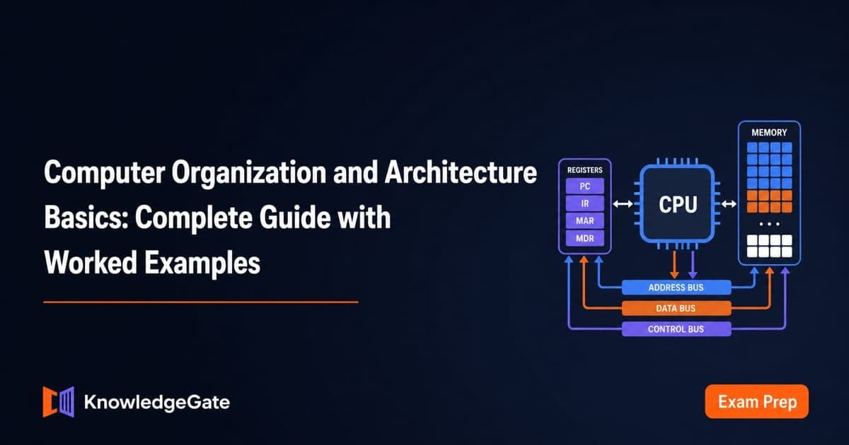
COA feels hard when registers, cache, buses and pipelines are memorised as disconnected terms. Then a simple numerical looks unfamiliar. For GATE CS preparation, follow one connected model: an instruction moving from bits into the CPU, through memory or I/O, and back as a result.
Related reading: cache memory organization and addressing modes and instruction formats.
What computer architecture and computer organisation cover
Computer architecture is the programmer-visible contract: instruction set, formats, addressing modes, registers, data types and address space. Computer organisation covers implementation choices such as control signals, buses, cache and pipelines. COA connects that contract to its hardware path.
In a stored-program computer, instructions and data are bits. The program counter fetches, the control unit decodes, the register file and arithmetic logic unit (ALU) execute, and memory or I/O completes a transfer.
The same architecture admits more than one organisation. Two teaching CPUs run the same binary: CPU S finishes each instruction in one 10 ns cycle, and CPU P splits that identical work into five overlapped 2 ns stages. Same contract, different hardware path, different timing.
Data representation, two's complement and overflow
A bit is one binary digit, a byte is eight bits, and a word is the CPU's natural width. Positional notation weights bits by powers of two. Unsigned n-bit range is 0 to 2^n - 1; two's-complement range is -2^(n-1) to 2^(n-1) - 1. Sign extension copies the sign bit when widening. See Number Systems and Base Conversions for the base recap.
Now add two 8-bit patterns:
  75 = 01001011
  60 = 00111100
       --------
 135 = 10000111
Unsigned 10000111 is 128 + 4 + 2 + 1 = 135. For its signed reading, invert to 01111000 and add one to get 121, so it represents -121. The sum 75 + 60 = 135 exceeds the signed 8-bit range -128 to 127, so overflow occurs. There is no ninth-bit carry-out. The tests differ.
To encode -37, begin with +37 = 00100101, invert the bits to 11011010, then add one: 11011011. The leading 1 is not a detachable minus sign. It participates in the encoding.
CPU building blocks and one complete instruction cycle
The program counter (PC) holds the next instruction address; the instruction register (IR) holds the current instruction. The memory address register (MAR) supplies an address, and the memory data register (MDR) carries its data. General-purpose registers hold operands and results. The ALU transforms values, buses move them, and the control unit directs both.
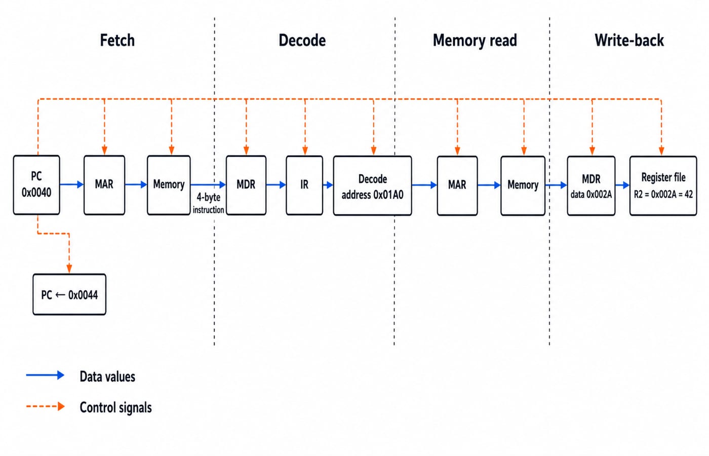
On a byte-addressed teaching CPU, PC = 0x0040. Its 4-byte instruction is LOAD R2, [0x01A0]; location 0x01A0 contains 0x002A.
Fetch:
MAR <- PCmakesMAR = 0x0040. Memory returns the encoded instruction through MDR into IR. The PC advances by four bytes to0x0044.Decode: the control unit identifies a load into R2 from address
0x01A0.Execute and memory read:
MAR = 0x01A0; memory returns0x002Athrough MDR.Write-back: the register file receives the value, leaving
R2 = 0x002A = 42decimal.
The datapath moved or transformed values. The control unit selected sources, destinations, memory read and register write.
CPU performance, CPI and pipeline throughput
CPU time depends on three quantities:
CPU time = instruction count x average CPI / clock rate
For 1.2 x 10^9 instructions, average cycles per instruction (CPI) of 1.5, and a 2.4 GHz clock:
CPU time = (1.2 x 10^9 x 1.5) / (2.4 x 10^9) = 1.8 / 2.4 = 0.75 s
If CPI falls to 1.2, time becomes (1.2 x 10^9 x 1.2) / (2.4 x 10^9) = 0.60 s. Speedup is 0.75 / 0.60 = 1.25x.
Pipelining improves throughput, not single-instruction latency. On CPU P, eight instructions ideally take (5 + 8 - 1) x 2 = 24 ns. CPU S, which never overlaps, needs 8 x 10 = 80 ns for the same eight, so the realised speedup is 80 / 24 = 3.33x, not the 5x the stage count suggests. A two-cycle stall on CPU P adds 2 x 2 = 4 ns, taking its time to 28 ns.
Structural, data and control hazards arise from resource conflicts, dependencies and uncertain instruction flow. Their stalls keep realised speedup below the stage count.
Memory hierarchy and a cache-address example
The hierarchy runs from registers through cache and main memory to secondary storage, trading capacity for speed at every step down. Temporal locality is reuse of the same address soon after touching it; spatial locality is use of addresses close to one just touched. Real programs show both, which is why a small fast cache pays for itself.
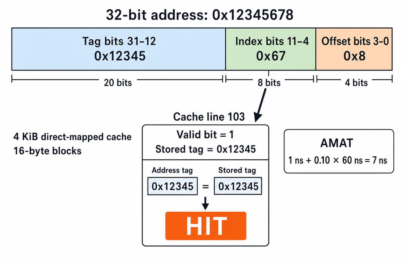
Take a direct-mapped 4 KiB cache, 32-bit byte addresses and 16-byte blocks. Its 4096 / 16 = 256 lines need 8 index bits; a block needs 4 offset bits. The remaining 32 - 8 - 4 = 20 bits form the tag:
20 tag bits | 8 index bits | 4 offset bits
Address 0x12345678 has tag 0x12345, index 0x67, and byte offset 0x8. Index 0x67 selects line 103. A hit also requires a set valid bit and stored tag 0x12345.
If cache lookup is 1 ns, hit rate is 90%, and the additional miss penalty is 60 ns, then AMAT = 1 + 0.10 x 60 = 7 ns.
Cache Memory: Mapping and Hit Ratio takes these mapping and hit calculations further.
Buses, I/O, interrupts and DMA
Address, data and control buses carry locations, values, and commands or timing. Programmed I/O polls; interrupt-driven I/O lets a device signal; direct memory access (DMA) delegates a block transfer. Polling suits a tiny predictable wait, interrupts avoid continuous polling, and DMA reduces CPU involvement.
A device raises 500 interrupts per second; each takes 400 ns including entry and exit. With a 2 ns CPU cycle, that is 400 / 2 = 200 cycles each. Total handling is 500 x 400 ns = 200,000 ns = 0.2 ms per second, or (0.2 / 1000) x 100 = 0.02%, before extra work.
The CPU finishes or safely pauses, saves required state, vectors to a handler, services the event and restores state. Details vary by architecture.
Size the DMA choice. Say the device delivers a 4 KiB block. Programmed I/O moving four bytes per transfer needs 4096 / 4 = 1024 transfers; at an assumed 50 cycles each on the 2 ns CPU that is 1024 x 50 x 2 = 102,400 ns of CPU time. DMA instead costs one setup of, say, 100 cycles (200 ns) plus one completion interrupt at the 400 ns above: about 600 ns, and the CPU is free while the block moves. That ratio is why block devices use DMA.
Common COA traps and preventive checks
Confusing bits with bytes gives a wrong address range. Write every unit.
Mixing word size with address width overstates capacity. Identify each width.
Treating overflow as carry-out misreads signed arithmetic. Recall that
135cannot fit even though no ninth-bit carry occurs.Clock rate alone ignores instruction count and CPI. Rebuild the
0.75 sresult.Assigning index bits before counting cache lines corrupts the split. Count lines first.
Calling an indexed line a hit ignores validity and tag. Check both.
Using a miss penalty without saying whether it is additional or total changes AMAT.
Multiplying performance by five ignores pipeline fill, drain and stalls. Start from the
24 nsschedule.
For a numerical: write units, state representation and width, name the formula, show powers of ten, then check direction and range.
How questions and interviews test COA
Question shapes include arithmetic interpretation, register-transfer traces, CPI comparisons, pipeline timing, cache fields, AMAT, and I/O trade-offs. Confirm current GATE topics and exam rules in the organising institute's official syllabus or bulletin.
For interviews, trace LOAD R2, [0x01A0]; justify why the 8-bit sum overflows only when signed; compare latency and throughput using 24 ns; and choose interrupts or DMA by naming transfer size, CPU involvement and responsiveness.
The short version
Bits determine how data is represented and interpreted. The instruction cycle connects the control unit to the datapath. Instruction count, CPI and clock rate jointly determine CPU time. Locality motivates the memory hierarchy. I/O mechanisms balance responsiveness against CPU involvement.
For structured full-subject learning, continue with GATE Guidance by Sanchit Sir. When you are ready to practise under test conditions, use the GATE Test Series.
Keep learning
Programmed I/O: Polling, CPU Utilisation, Worked Examples and GATE Question Patterns
Follow one programmed-input transfer from control write to data read, then calculate how many polls one word costs and what a longer poll period buys.
Updated 7 Oct 20266 min readComputer Organization & Architecture
Multiprocessor Fundamentals: Architecture, Speedup and Worked Examples
Build a clear model of multiprocessor systems, then use it to calculate speedup and efficiency, trace a coherent write, and diagnose a lost update.
Updated 2 Oct 20265 min readComputer Organization & Architecture
Multiprocessor Classification: Flynn Taxonomy, Memory Models and Exam-Style Worked Examples
Learn how to choose the right multiprocessor classification axis, then solve a four-lane SIMD trace and a NUMA average-access-time problem step by step.
Updated 27 Sep 20266 min readComputer Organization & Architecture
Interrupt-Driven I/O Explained: CPU Handshake, Worked Timing Example and GATE Traps
Trace an interrupt from device request to return-from-interrupt, then compare polling, per-event interrupts, and DMA through worked timing examples.
Updated 25 Sep 20267 min readComputer Organization & Architecture