Synchronous Counter Analysis: Two Worked State Sequences for GATE
Analyse two three-bit synchronous counters step by step. One produces a binary MOD-8 sequence, while the other shows how unused states can trap a circuit.
KnowledgeGate Team
Exam prep & CS education
Updated 21 Aug 20265 min read
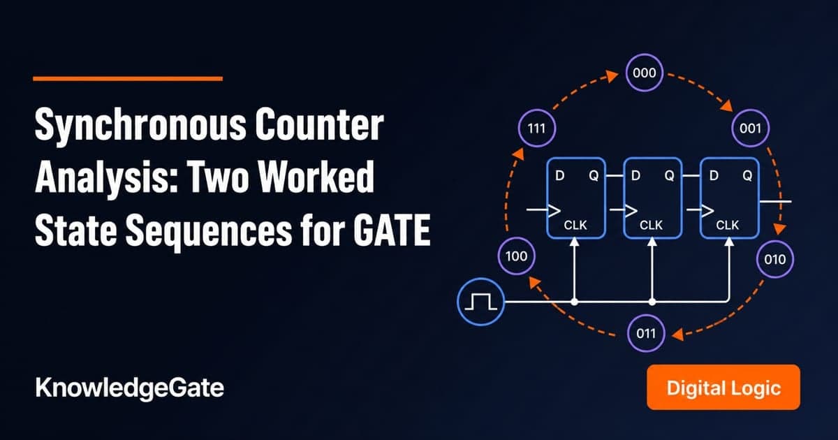
A counter circuit may give you flip-flop inputs and logic gates, yet its sequence is not safe to guess from its shape. Three flip-flops do not automatically make a binary MOD-8 counter. Correct analysis evaluates every flip-flop input from the same old state, just before the common active edge. That rule turns one three-bit JK circuit into a clean binary MOD-8 loop, and it exposes a three-bit D circuit whose six-state loop leaves two states trapped outside it.
Synchronous counter analysis starts with the common clock and given logic
In a synchronous counter, all flip-flops respond to the same active clock edge. In a ripple counter, one flip-flop output clocks another, so changes propagate in stages.
A complete analysis should produce five things:
Flip-flop input equations.
Next-state equations.
A complete present-state and next-state table.
A state diagram with every cycle and its length.
Timing or output-frequency behaviour.
For the broader map of latches, flip-flops, registers, and counters, review Sequential Circuits: Flip-Flops and a Worked Counter Design.
Here, Q2 is the most significant bit and Q0 is the least significant bit. Q2 Q1 Q0 denotes the present state, Q(next) is the value immediately after the active edge, and a prime such as Q2' means logical complement.
Flip-flop characteristic equations drive counter analysis
Use the characteristic equation for the flip-flop in the circuit:
D flip-flop:
Q(next) = DT flip-flop:
Q(next) = Q XOR TJK flip-flop:
Q(next) = JQ' + K'Q
When a JK flip-flop has J = K = X, it holds for X = 0 and toggles for X = 1.
A characteristic table and an excitation table answer opposite questions. Analysis knows the inputs and asks for Q(next), so use the characteristic rule. Design knows the desired transition and asks for suitable inputs, so use the excitation table.
The old-state rule is essential. At present state 011, every expression containing Q2, Q1, or Q0 must use 0, 1, and 1 until all three next bits are known. Never reuse a newly calculated bit on the same edge. For difficult input logic, revise Boolean Algebra and K-Map Minimization.
Worked example 1: analyse a three-bit JK binary counter
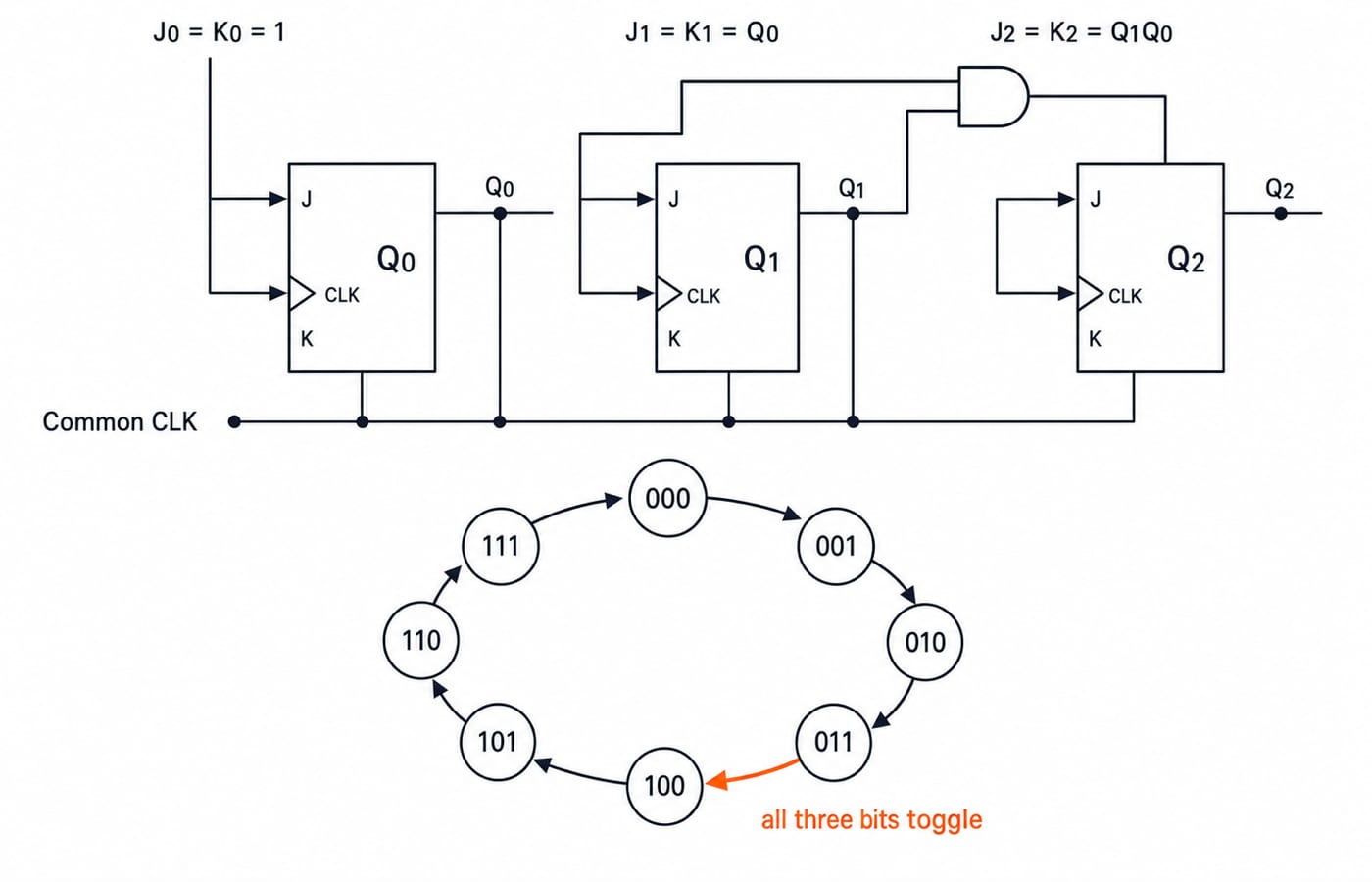
Three positive-edge-triggered JK flip-flops share one clock. Their inputs are:
J0 = K0 = 1J1 = K1 = Q0J2 = K2 = Q1Q0
Treat each tied JK pair as a toggle input. The next-state equations are:
Q0(next) = Q0 XOR 1 = Q0'Q1(next) = Q1 XOR Q0Q2(next) = Q2 XOR (Q1Q0)
The complete table is:
Present | Toggle inputs | Next |
|---|---|---|
|
|
|
|
|
|
|
|
|
|
|
|
|
|
|
|
|
|
|
|
|
|
|
|
At 011, old Q0 = 1 makes Q1 toggle, and old Q1Q0 = 1 x 1 = 1 makes Q2 toggle. Since Q0 always toggles, 0 1 1 becomes 1 0 0.
At 100, old Q0 = 0 makes Q1 hold, and old Q1Q0 = 0 x 0 = 0 makes Q2 hold. Only Q0 toggles, giving 101. All eight states form one binary up-counting cycle, so its modulus is 8.
Timing and modulus come from the verified state sequence
Starting from 000, the sampled state after each rising edge is:
edge 0: 000, edge 1: 001, edge 2: 010, edge 3: 011, edge 4: 100, edge 5: 101, edge 6: 110, edge 7: 111, edge 8: 000.
The sequence returns after eight clock periods, so Tcounter = 8Tclock. The sampled bit patterns are:
Q0:0,1,0,1,0,1,0,1,0Q1:0,0,1,1,0,0,1,1,0Q2:0,0,0,0,1,1,1,1,0
For this binary sequence, fQ0 = fclock/2, fQ1 = fclock/4, and fQ2 = fclock/8.
Three flip-flops provide at most eight states. A custom counter can use fewer or split them across cycles. Power-of-two division follows from this sequence, not merely from three flip-flops or a common clock.
Worked example 2: expose a MOD-6 cycle and lockout
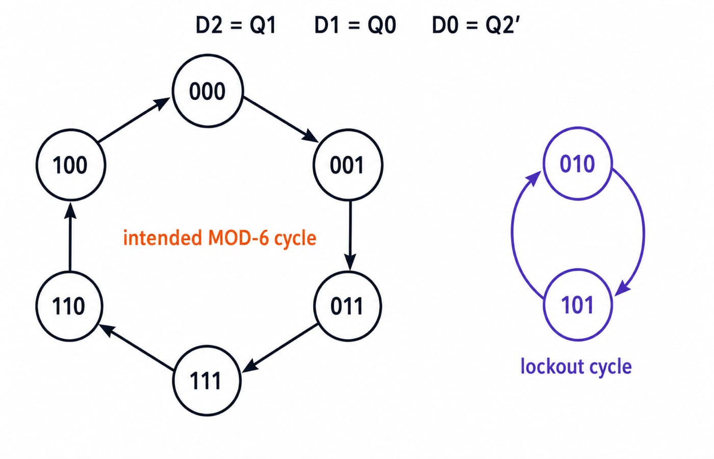
Take three common-clock D flip-flops with D2 = Q1, D1 = Q0, and D0 = Q2'. Since Q(next) = D, substitute the present-state bits:
Present | Next |
|---|---|
|
|
|
|
|
|
|
|
|
|
|
|
|
|
|
|
From 000, trace 000 -> 001 -> 011 -> 111 -> 110 -> 100 -> 000. Its six unique states make the intended cycle MOD-6.
The remaining states form a separate lockout cycle, 010 -> 101 -> 010. The circuit is not self-starting because either initial state stays trapped. These are not don't-cares during analysis. They are possible power-up states unless reset or corrected next-state logic guarantees recovery.
Analysis traps come from updating too early or assuming too much
Updating too early: using
Q0(next)inside theQ1equation creates ripple-style sequential updating. Evaluate every input from the old state.Using an excitation table: this reverses an analysis problem. Use the characteristic equation when inputs are already known.
Assuming three bits mean MOD-8: the D circuit disproves this. Count unique states in the actual reachable loop.
Stopping at the intended loop: analyse all
2^npossible states when self-starting matters, and draw every disconnected cycle.
A reset selects a starting state but does not prove recovery from every invalid state. Synchronous circuits still have combinational delay between outputs and inputs, but all state bits are sampled together at the active edge. Do not draw ripple-style staged transitions.
GATE questions test analysis, modulus, timing, and lockout
The official GATE 2026 CS syllabus lists combinational and sequential circuits under Digital Logic.
Practise computing one next state, completing a state table, identifying a standard or custom sequence, finding modulus and frequency, detecting lockout, distinguishing synchronous from ripple clocking, and reverse-checking the toggle condition.
Use this five-step order:
Write the input equations.
Apply the correct characteristic equation.
Fill all
2^nstate-table rows.Trace every cycle.
Answer the requested quantity from the verified result.
Over 40 questions on synchronous counter analysis are available to practise on KnowledgeGate. The GATE CS Exam Preparation category places them alongside the rest of Digital Logic.
The short version and the next study step
Keep five checks together: a common clock does not imply binary order; old values feed every next-state equation; the complete table proves the sequence; unique states determine modulus; and unused states must be tested for recovery or lockout.
The JK equations generate one eight-state binary loop, with clock division by 2, 4, and 8 at Q0, Q1, and Q2. The D equations generate a six-state intended loop plus the trapped 010 <-> 101 loop.
Use GATE Guidance by Sanchit Sir when you want Digital Electronics placed inside a complete subject-wise GATE study sequence.
Keep learning

Functional Completeness in Digital Logic: NAND, NOR and Worked Examples
Learn what makes a Boolean operator set complete, how NAND and NOR recover a standard basis, and how to verify a four-gate NAND construction.
Updated 2 Oct 20266 min readDigital Logic
Boolean Function Counts: Formulas, Worked Examples and Exam Traps
Build the master Boolean-function formula from output choices, then learn how common restrictions change the count through combinations, pairing and inclusion-exclusion.
Updated 27 Sep 20266 min readDigital Logic

Analog-Digital Conversion Basics: ADC, DAC, Worked Examples and Exam Patterns
Build ADC and DAC basics from one consistent transfer model, then practise code selection, reconstruction error, flash and SAR conversion, and bit-depth calculations.
Updated 25 Sep 20266 min readDigital Logic

Universal Realization with NAND and NOR Gates: Concepts, Worked Example and Exam Patterns
Learn why NAND and NOR are universal, then implement one three-variable function using four NAND gates and four NOR gates with verified input traces.
Updated 23 Sep 20265 min readDigital Logic