

Logic Families and Hardware Explained: TTL, CMOS, Fan-Out and Delay
Learn how physical gates satisfy voltage, current and timing limits. Two worked examples show how to test noise margins, loading, delay and compatibility.
KnowledgeGate Team
Exam prep & CS education
Updated 27 Oct 20265 min read

A truth table tells you what a gate should do, but a physical gate must also produce valid voltages, source or sink enough current, switch in time and tolerate noise. That is where learners often mix up Boolean logic with real hardware. The electrical limits determine noise margin, fan-out, propagation delay and power-delay product for TTL, CMOS and ECL. Use guaranteed limits rather than typical values or family-name folklore.
A Logic Family Is Hardware, Not a New Boolean Function
A logic family is a set of circuits with related device technology and compatible electrical conventions. AND, OR, NAND and XOR are functions; TTL, CMOS and ECL are hardware approaches. Two NAND gates can share a truth table but differ in thresholds, drive, delay and power.
For bits, gate notation and simplification laws, start with Digital Fundamentals and Boolean Algebra Explained. Logic-family analysis begins where voltage, current and timing limits matter.
Fan-in counts gate inputs. Fan-out counts loads one output can safely drive. The GATE CS Exam category places this in wider preparation.
Electrical Parameters Behind a Valid 0 and 1
The min and max qualifiers mark guarantees, not typical readings.
Parameter | Meaning |
|---|---|
| Minimum guaranteed HIGH output voltage |
| Maximum guaranteed LOW output voltage |
| Minimum input voltage certainly read as HIGH |
| Maximum input voltage certainly read as LOW |
Between VIL(max) and VIH(min), the input is undefined. The margins are:
NMH = VOH(min) - VIH(min)
NML = VIL(max) - VOL(max)
A positive result is headroom; zero or a negative result is unsafe.
IOH and IOL are HIGH and LOW drive limits; IIH and IIL are one input's demands. Use magnitudes for fan-out. tPLH and tPHL are propagation delays. Under the average convention, tpd = (tPLH + tPHL) / 2 and PDP = power × tpd.
TTL, CMOS and ECL Compared by Circuit Idea
Family | Architecture-level idea | Useful tendency, not a universal ranking |
|---|---|---|
TTL | Bipolar-junction-transistor stages | Classic inputs draw non-zero current; source and sink limits are often asymmetric |
CMOS | Complementary MOSFET pull-up and pull-down networks | Very high DC input resistance, but input capacitance matters |
ECL | Differential bipolar structure that avoids transistor saturation | Continuous current and a small voltage swing support fast switching |
CMOS dynamic power rises with activity, load capacitance and supply voltage squared. Subfamilies overlap, so supplied data or the manufacturer's datasheet wins.
Multiplexers, decoders and adders need hardware. Equations determine the result; family and load determine whether it arrives valid and on time.
Worked Logic-Family Example: Margins, Fan-Out, Delay and PDP
Consider a hypothetical 5 V gate. These guarantees apply only here.
Parameter | Given value |
|---|---|
|
|
|
|
|
|
|
|
Magnitude of |
|
|
|
|
|
Magnitude of |
|
|
|
|
|
average power |
|
Calculate both margins:
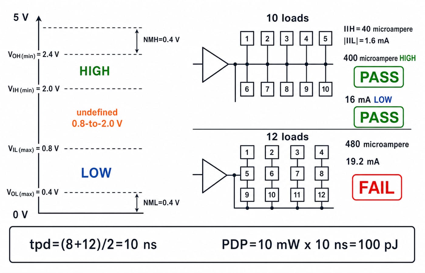
NMH = 2.4 - 2.0 = 0.4 V
NML = 0.8 - 0.4 = 0.4 V
Each output has 0.4 V of guaranteed headroom. Supply voltage and typical values do not enter these subtractions.
Check both current directions:
HIGH fan-out = 0.4 mA / 40 microampere = 400 microampere / 40 microampere = 10
LOW fan-out = 16 mA / 1.6 mA = 10
Safe DC fan-out is min(10, 10) = 10. Eight loads demand 8 × 40 = 320 microampere <= 400 microampere HIGH and 8 × 1.6 = 12.8 mA <= 16 mA LOW, so both pass. Twelve demand 480 microampere > 400 microampere and 19.2 mA > 16 mA, so both fail.
tpd = (8 + 12) / 2 = 10 ns, giving:
PDP = 10 mW × 10 ns = 100 pJ
In base units, 10 × 10^-3 W × 10 × 10^-9 s = 100 × 10^-12 J. Smaller PDP is better by this measure, but delay and power remain separate.
Interfacing Logic Families: Voltage Is Not Enough
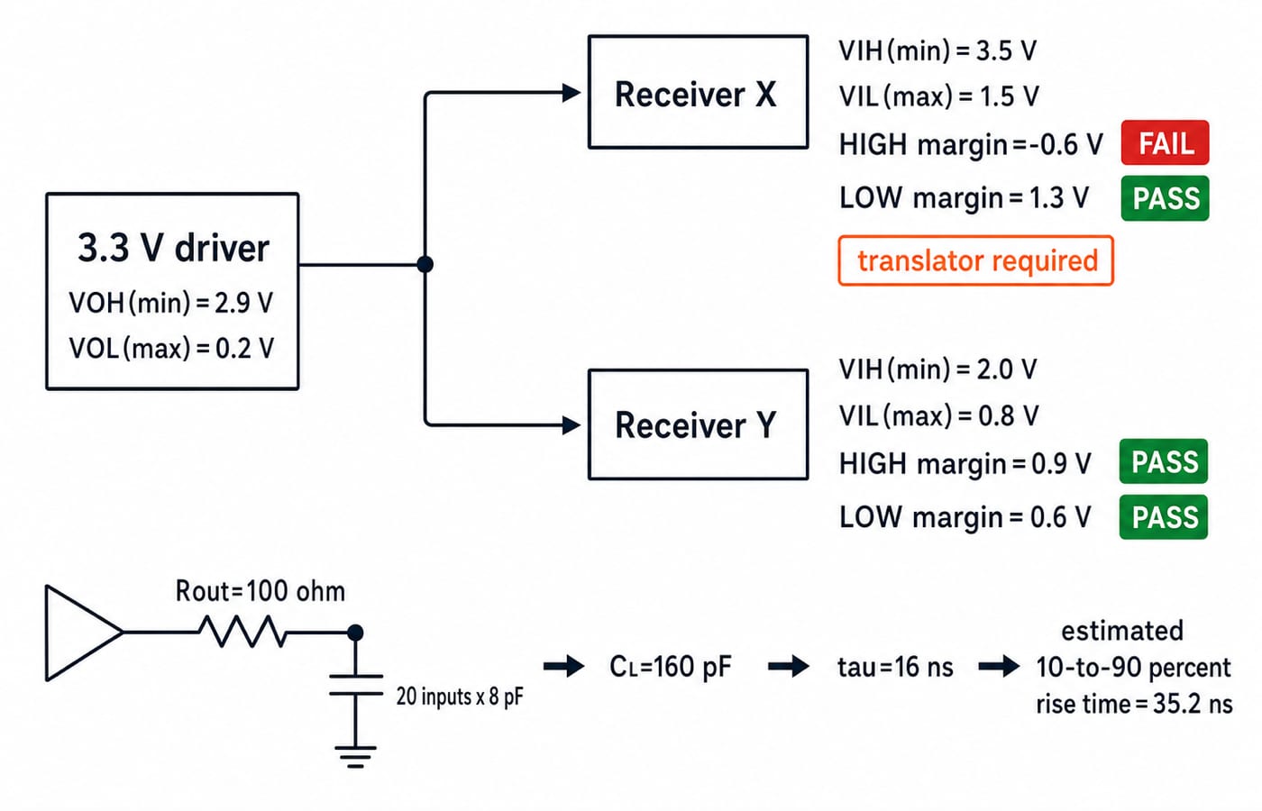
A 3.3 V driver guarantees VOH(min) = 2.9 V and VOL(max) = 0.2 V. Receiver X needs VIH(min) = 3.5 V and permits VIL(max) = 1.5 V:
HIGH margin = 2.9 - 3.5 = -0.6 V, so HIGH fails.
LOW margin = 1.5 - 0.2 = 1.3 V, so LOW passes.
Both states must pass, so Receiver X may need a level translator. Receiver Y's VIH(min) = 2.0 V and VIL(max) = 0.8 V give 0.9 V and 0.6 V, so it passes.
CMOS DC fan-out is not infinite. Twenty 8 pF inputs give CL = 20 × 8 = 160 pF. With Rout = 100 ohm, tau = Rout × CL = 16 ns; the first-order 10-to-90 percent rise-time estimate is 2.2 tau = 35.2 ns. This RC estimate is not datasheet delay. Check the real edge.
Check ground, supply range, absolute-maximum pins, edge restrictions and output type: push-pull, open-collector, open-drain or tri-state. Never join push-pull outputs. Sequential Circuits: Flip-Flops and Counters covers setup, hold and clock-edge quality.
Common Logic-Family Traps and Their Fixes
Match guaranteed limits by state. One positive margin cannot cancel a negative one.
Find HIGH and LOW fan-out separately, round down, and take the smaller whole number. Never average them.
Fan-in is not fan-out, and current compatibility does not prove acceptable capacitive edge speed.
Never float unused CMOS inputs, join push-pull outputs, or infer compatibility from a shared supply or family name. Read the limits.
Propagation delay times the response; rise and fall time describe the transition. Static CMOS power may be low while switching power is not. Without complete values, use only
Pdynamicproportional toCL × VDD^2 × f.
How Exams Test Logic-Family Hardware
Exam-style tasks ask for margins, fan-out, interface compatibility, average delay, PDP, or a device choice. Family-order questions require named subfamilies and supplied values, not blanket rules.
Try this rapid check:
VOH = 3.8 V,VIH = 3.2 V:NMH = 0.6 V.VIL = 0.70 V,VOL = 0.25 V:NML = 0.45 V.IOL = 8 mA,|IIL| = 0.4 mA: LOW fan-out is20.HIGH fan-out
25, LOW fan-out16: safe fan-out is16.tPLH = 6 ns,tPHL = 10 ns, power5 mW:tpd = 8 ns,PDP = 40 pJ.
More than 20 questions on this topic are live in our practice bank. Use the GATE Test Series for timed practice after reproducing these steps.
Logic Families: The Short Version and Next Step
Function is not family.
NMH = VOH(min) - VIH(min).NML = VIL(max) - VOL(max).Safe fan-out is the smaller whole HIGH or LOW current ratio.
tpd = (tPLH + tPHL) / 2only under the stated average convention.PDP = P × tpd, with the units reduced to energy.
Results: 0.4 V margins, fan-out 10, delay 10 ns, PDP 100 pJ. Recalculate the 8-load and 12-load cases, then test both receivers from guaranteed limits.
GATE Guidance by Sanchit Sir provides a sequenced Digital Electronics path including Logic Gates & Hardware. The function says what a circuit should do; the electrical limits say whether it will do so reliably.
Keep learning

Base Conversion Explained: Binary, Octal, Decimal and Hexadecimal Worked Examples
Learn one reliable workflow for converting integers and fractions across bases, with checked examples, shortcut rules and quick questions for practice.
Updated 26 Oct 20267 min readDigital Logic

Flip-Flop Conversion Explained: Tables, K-Maps and a Worked D-to-JK Design
Learn a repeatable flip-flop conversion method, then derive and verify the combinational logic that makes a D flip-flop behave exactly like a JK flip-flop.
Updated 25 Oct 20265 min readDigital Logic

NOT, OR and AND Gates: Evolution, Truth Tables and a Worked Circuit
Learn how NOT, OR and AND gates developed from switching ideas, then trace F=(A+B')C node by node and confirm it with a complete truth table.
Updated 23 Oct 20265 min readDigital Logic

Binary Arithmetic Operations Explained: Rules and Worked Examples
Learn binary addition, subtraction, multiplication and division with aligned worked examples, then separate carry, borrow and two's-complement overflow.
Updated 19 Oct 20266 min readDigital Logic