

Program Control and I/O Handling in the Basic Computer: Instructions, Worked Traces and Exam Patterns
Trace exact PC changes, ready flags, polling and interrupt service in Mano's Basic Computer, from a subroutine call to an ASCII A-to-B I/O program.
KnowledgeGate Team
Exam prep & CS education
Updated 5 Nov 20267 min read

A correct trace depends on when PC was incremented, whether a branch is direct or indirect, which ready flag is tested, and which instruction clears it. BUN, BSA, and ISZ alter control flow; I/O instructions use ready flags for input, output, polling, and interrupts, including an ASCII A-to-B trace and an interrupt return with exact addresses. The addresses and micro-operations follow Mano's 16-bit Basic Computer model. For the broader syllabus path, use GATE CS Exam Preparation.
Program Control and I/O Handling: Fix the Basic Computer Model First
The Basic Computer stores a 16-bit word and uses a 12-bit address. Its main registers here are the 12-bit program counter PC, 16-bit accumulator AC, 8-bit input and output registers INPR and OUTR, ready flags FGI and FGO, and interrupt-enable flip-flop IEN.
During fetch, the processor reads the instruction at PC and advances PC to the next sequential address before execution.
A memory-reference instruction contains an indirect bit, a three-bit opcode, and a 12-bit address. Opcode 111 selects register-reference instructions when the top control bit is 0, and I/O instructions when it is 1; low function bits identify the operation.
Program control changes the next address through branching, skipping, subroutines, or I/O. For effective-address groundwork, review Addressing Modes and Instruction Formats.
BUN, BSA and ISZ: Program Control with Exact PC Changes
BUN transfers control unconditionally to the effective address. Direct BUN 450 makes the next PC equal decimal 450. Indirect BUN I 450 reads the 12-bit address stored in M[450] and loads that into PC. It does not branch to 451.
BSA calls a subroutine by using an inline memory cell for the return address. Suppose BSA 450 is at decimal address 120. Fetch has already changed PC to 121. Execution writes M[450] = 121 and sets PC = 451, so the subroutine starts at 451. Its final BUN I 450 reads the saved address and restores PC = 121. No hardware stack is involved.
ISZ performs M[EA] <- M[EA] + 1, then increments PC once more only if the 16-bit result is zero. If M[500] = 0xFFFE, the result is 0xFFFF, so there is no skip. If M[500] = 0xFFFF, adding one wraps to 0x0000, so the next instruction is skipped. This is useful for loop counters, but it is not a general comparison instruction.
INP, OUT, SKI, SKO, ION and IOF: The I/O Contract
An input device places an 8-bit value in INPR and sets FGI = 1. An output device sets FGO = 1 when it can accept a byte. The processor checks the matching flag first.
Instruction | Exact effect |
|---|---|
| Copy |
| Copy |
| Skip the next instruction when |
| Skip the next instruction when |
| Set |
| Clear |
SKI and SKO are conditional control actions in the I/O group. Polling repeatedly tests a flag, spending processor cycles but keeping control simple. Interrupt mode lets the main program continue until a ready flag and IEN create a request; entry, service, and return have overhead.
The cost of that spinning, measured as polls per arriving word and as a share of the CPU, is worked out in Programmed I/O: Polling and CPU Utilisation. Here the same loop appears as SKI followed by BUN, and the question is only what PC does next.
For the machine-independent view — the three interface registers, memory-mapped versus isolated addressing and DMA cycle stealing — use Input Output Organisation in COA. Mano's Basic Computer instead exposes the same ideas as named instructions and visible flag bits: FGI, FGO, IEN and the exact PC change at every step.
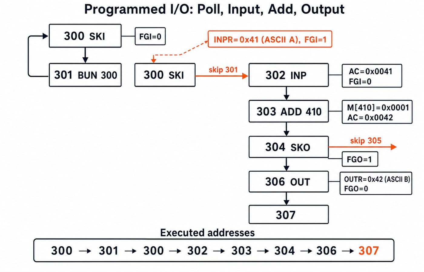
Worked Programmed-I/O Trace: Read A, Produce B, Then Output It
Use decimal addresses and 16-bit hexadecimal data:
300  SKI
301  BUN 300
302  INP
303  ADD 410       M[410] = 0x0001
304  SKO
305  BUN 304
306  OUT
307  HLT
Initially, PC = 300, AC = 0x0000, FGI = 0, and FGO = 1. The first SKI does not skip, so BUN 300 repeats the loop. Before the next SKI, the keyboard places ASCII A = 0x41 in INPR and sets FGI = 1.
Step | Executed address | Condition or action | Next PC | AC | FGI | FGO | INPR/OUTR |
|---|---|---|---|---|---|---|---|
1 | 300 |
| 301 |
| 0 | 1 | Not ready |
2 | 301 | Branch to 300 | 300 |
| 0 | 1 | Not ready |
3 | 300 |
| 302 |
| 1 | 1 |
|
4 | 302 | Input low byte, clear input flag | 303 |
| 0 | 1 |
|
5 | 303 |
| 304 |
| 0 | 1 |
|
6 | 304 |
| 306 |
| 0 | 1 | Output ready |
7 | 306 | Copy low byte, clear output flag | 307 |
| 0 | 0 |
|
8 | 307 | Halt | 308, halted |
| 0 | 0 |
|
Thus ADD 410 produces ASCII B = 0x42. The key next-address progression is 300 -> 301 -> 300 -> 302 -> 303 -> 304 -> 306 -> 307.
Interrupt-Driven I/O: Save PC, Service the Device and Return
What a general processor saves and restores at an interrupt boundary, how a vector table selects the handler, and at what event rate interrupts beat polling are covered in Interrupt-Driven I/O Explained. The Basic Computer makes the same mechanism concrete and minimal: one saved word at M[0], one fixed service address, one return instruction.
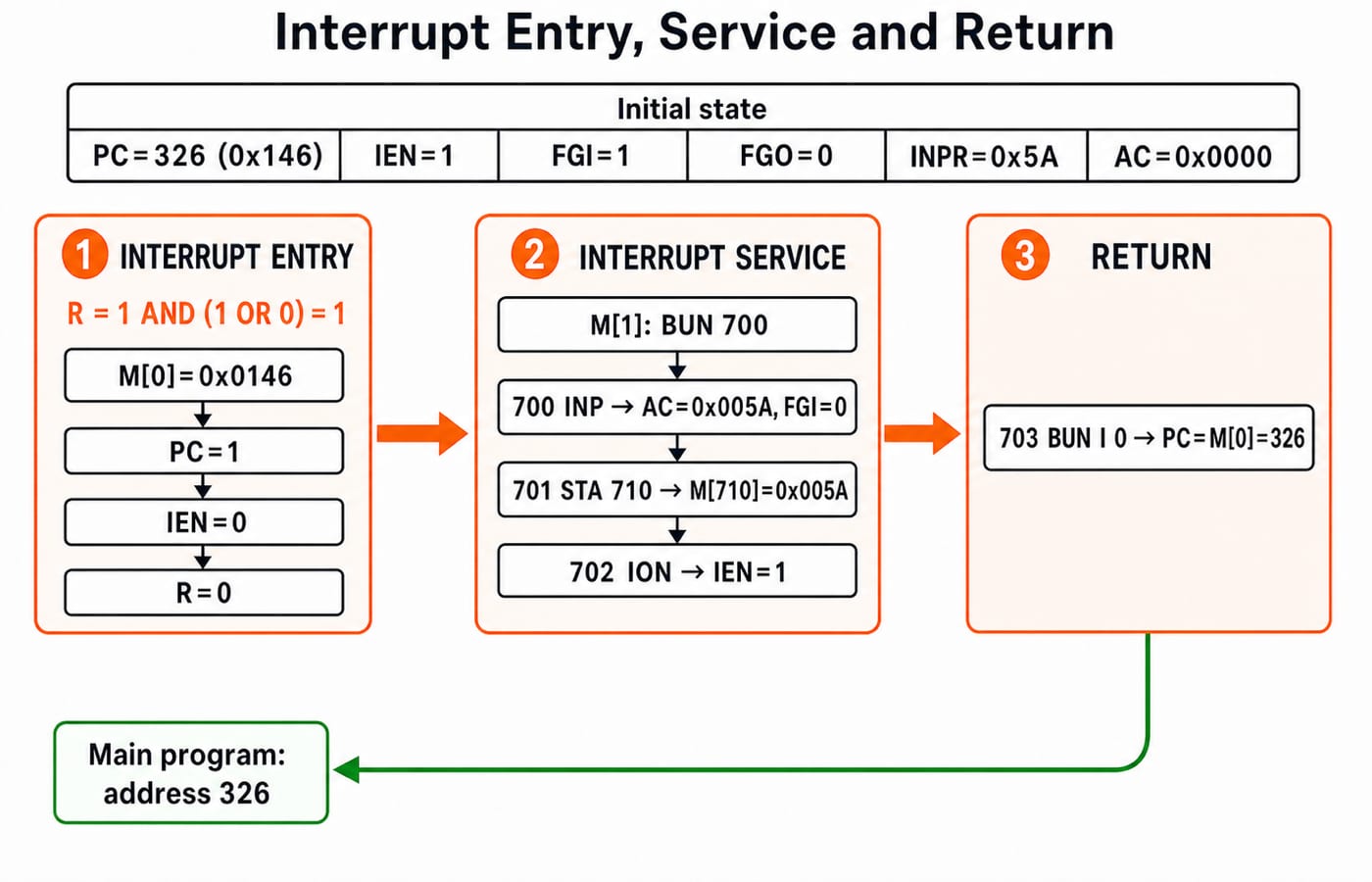
The request condition is R = IEN AND (FGI OR FGO), sampled after an instruction completes. When it is true, the interrupt cycle replaces the next normal fetch. The machine copies the current PC to temporary storage, writes that return address into M[0], sets PC = 1, then clears IEN and R. In this model, address 0 holds the return address and service begins at address 1.
Suppose the instruction at decimal 325 has completed, making PC = 326 = 0x146. Let IEN = 1, FGI = 1, FGO = 0, INPR = 0x5A (ASCII Z), and AC = 0x0000. Then R = 1 AND (1 OR 0) = 1. Interrupt entry writes M[0] = 0x0146, sets PC = 1, and clears IEN and R.
Let M[1] contain BUN 700. The service routine is:
700  INP
701  STA 710
702  ION
703  BUN I 0
INP makes AC = 0x005A and clears FGI. STA 710 writes M[710] = 0x005A. ION restores IEN = 1. Finally, BUN I 0 reads the saved 12-bit address from M[0] and restores PC = 326. Both ready flags are now 0, so enabling interrupts does not immediately request service again. A real routine must handle or mask every enabled source before returning.
Program Control and I/O Exam Questions: Trace These Traps Explicitly
Program Control & I/O Handling MCQs: 12 Solved PYQs mixes Basic Computer questions with 8085 loops, flags and I/O handshakes. Mano's 16-bit model instead links BUN, BSA, ISZ, ready flags and interrupt-state changes within one architecture.
Practise these question forms as state traces:
next addresses for direct and indirect
BUNlinkage through
BSAandBUN Izero-wrap and skip behaviour for
ISZflag and low-byte changes after
INPorOUTpolling-loop exits through
SKIorSKOthe return address saved during interrupt entry
Check these worked values:
After
BSA 450at address120,M[450] = 121andPC = 451.After
ISZ 500changes0xFFFF,M[500] = 0x0000and one instruction is skipped.After the programmed trace's
INP,AC = 0x0041andFGI = 0.After interrupt entry,
M[0] = 326andPC = 1.
The common traps are forgetting that fetch already advanced PC, treating BSA as a stack call, testing the old rather than incremented ISZ value, reversing the meaning of ready flag 1, and assuming ION itself jumps to the service routine. These answers apply to the stated Basic Computer model.
Program Control and I/O Handling: The Short Version and Next Step
BUN changes PC; BSA saves a return address and enters a subroutine; ISZ, SKI, and SKO conditionally skip. INP and OUT move one byte and clear its flag. An interrupt saves the current PC at M[0], services from address 1, and returns through BUN I 0.
Redraw both diagrams and recompute the four checks before attempting the questions. Use GATE Guidance by Sanchit Sir for the full COA sequence.
Keep learning

Program Control & I/O Handling MCQs: 12 Solved PYQs with Explanations
Practise 12 PYQs on program control and I/O handling. Trace PCs, memory overwrites, registers, flags, loops and interrupt handshakes step by step.
Updated 30 Oct 20267 min readComputer Organization MCQs
Python Exception Handling Explained: try, except, finally, Raising Errors and Worked Traces
Learn one reliable model for Python exceptions through a four-record score parser, handler matching, propagation, cleanup, and solved output traces.
Updated 19 Nov 20265 min readPython
Python Control Flow and Looping: if, for, while and Worked Traces
Trace Python if, for and while execution through branch order, range boundaries, number reversal, loop jumps, nesting and edge cases.
Updated 13 Nov 20267 min readPython

If-Else Statements in C: Basic, Nested and Advanced Control Flow with Worked Traces
Learn how C chooses a branch, then trace ladders, nested decisions, short-circuit expressions and common output traps with exact values.
Updated 26 Oct 20266 min readC Programming & Data Structures