Intro & Byte Stuffing MCQs: 11 Solved Framing Questions with Explanations
Solve 11 framing MCQs covering frame boundaries, byte stuffing, synchronous and asynchronous transmission, throughput, LAN encapsulation and TDM.
KnowledgeGate Team
Exam prep & CS education
27 Aug 20268 min read
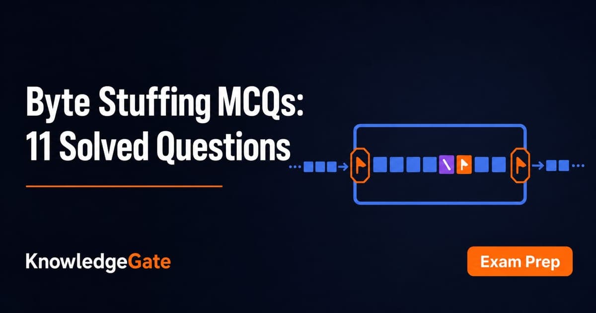
Framing questions mix delimiter rules with small arithmetic traps. A reliable solution separates the boundary rule from the transmission unit: fixed-length frames use their size, byte-oriented protocols escape every payload control byte, and asynchronous throughput includes start, stop and parity overhead. Choose an answer before reading its explanation. Q1 is an MSQ, so more than one choice is correct. For wider practice, use the Computer Networks MCQs collection.
1. Framing fundamentals MCQs: Q1-Q4
A frame is the Data Link Layer unit that turns a continuous bit stream into distinguishable blocks. A known fixed size supplies an implicit boundary, while a variable-size frame needs an explicit boundary method.
Term | Job | Common confusion |
|---|---|---|
Frame | Data Link Layer block | Not an arbitrary segment |
Character count | Gives frame length | Corruption shifts later boundaries |
Flag | Marks a boundary | A payload flag needs escaping |
Escape byte | Protects control bytes | Receiver preserves the following byte |
Q1. Fixed-size and variable-size framing
Which of the following correctly describes Framing?
A. The DLL needs to pack bits in segments, so that each segment is distinguishable from one another.
B. In fixed-size framing, there is no need for defining the boundaries of the frames; the size itself can be used as a delimiter.
C. In variable-size framing, we need a way to define the end of the frame and the beginning of the next.
D. Both A and C
Answer: Options B and C are correct. In fixed-size framing, the frame size itself defines the boundaries, while variable-size framing needs a way to mark where one frame ends and the next begins. "Both A and C" is incorrect because it includes A, which merely restates the goal of making segments distinguishable instead of giving a boundary method.
Q2. What frame design includes (Bihar STET 2025)
Frame design in the Data Link Layer includes:
A. Deciding the routing path for data packets
B. Defining the structure of data frames
C. Assigning IP addresses to devices
D. Setting the data transmission rate
Answer: Defining the structure of data frames. Routing and IP addressing are Network Layer concerns, while rate belongs to the Physical Layer. Frame design organises Data Link fields and boundaries.
Q3. Main purpose of Data Link Control (Bihar STET 2025)
What is the main purpose of the Data Link Control in the data link layer?
A. Error correction
B. Data encryption
C. Data routing
D. Data framing
Answer: Data framing. Data Link Control organises the raw stream into frames. Protocols may also handle errors and flow, but encryption and routing are separate.
Q4. Character Count framing failure
Which of the following is a disadvantage of Character Count framing in Data Link Layer?
A. Overhead of stuffing bits increases
B. Inefficient for binary data transmission
C. Requires special flag sequence to mark frames
D. Loss of synchronization if count field is corrupted
Answer: Loss of synchronization if count field is corrupted. If 5 becomes 7, the receiver consumes two next-frame characters and misses the boundary. This is a count failure, not stuffing or a required flag.
2. Byte stuffing MCQ: trace every ESC and FLAG in Q5
At the sender, replace every source ESC with ESC ESC and every source FLAG with ESC FLAG, while ordinary bytes pass unchanged. At the receiver, strip each inserted escape and preserve the byte that follows it. Apply this rule from left to right to every byte in the source stream. A common trap is to stop after the first control byte instead of escaping every occurrence.
Q5. Output of the byte-stuffing algorithm
A data fragment A B ESC C ESC FLAG FLAG D occurs in the middle of a data stream. Using the byte-stuffing algorithm, where:
Every occurrence of ESC is replaced with ESC ESC, and
Every occurrence of FLAG is replaced with ESC FLAG.
What is the output of the byte-stuffed stream?
A. A B ESC ESC C ESC ESC FLAG ESC FLAG D
B. A B ESC ESC C ESC ESC ESC FLAG ESC FLAG D
C. A B ESC ESC C FLAG FLAG D
D. A B C FLAG FLAG D
Answer: A B ESC ESC C ESC ESC ESC FLAG ESC FLAG D. Each source ESC becomes ESC ESC, each source FLAG gains a leading ESC, and ordinary bytes pass through unchanged. The near-miss stream A B ESC ESC C ESC ESC FLAG ESC FLAG D leaves the first FLAG unescaped. The two shorter streams A B ESC ESC C FLAG FLAG D and A B C FLAG FLAG D drop or expose control bytes.
3. Character boundaries in synchronous and asynchronous transmission: Q6-Q7
Boundary marking differs from bit-clock recovery. Asynchronous transfer resynchronises each byte with a start bit and recognises stop or idle with stop bits. Synchronous streams use control information for boundaries and separate fields for error detection.
Q6. Purpose of a control character around a synchronous block
A control character is sent at the beginning as well as at the end of each block in the synchronous-transmission in order to
A. Synchronize the clock of transmitter and receiver.
B. Supply information needed to separate the incoming bits into individual character.
C. Detect the error in transmission and received system.
D. Both (A) and (C).
Answer: Supply information needed to separate the incoming bits into individual character. These boundary characters divide the stream into individual characters. Clock synchronization and error detection are handled by separate mechanisms, so the choice that combines them is wrong.
Q7. Start and stop padding in asynchronous serial transfer (GATE 2002)
In asynchronous serial data transmission, every byte of data is padded with a '0' at the beginning and one or two '1's at the end because:
A. The receiver is to be synchronized for byte reception
B. The receiver recovers lost '0' and '1' bits from these padded bits
C. The padded bits are useful in parity computation
D. None of these
Answer: The receiver is to be synchronized for byte reception. Leading 0 starts the byte, while trailing 1 or 1 1 indicates stop against idle. They neither restore payload nor enter parity.
4. Asynchronous transmission throughput numericals: Q8-Q9
Use bits per character = data + parity + start + stop, then characters per second = line bit rate / bits per character. Keep the two units separate.
Q8. Characters per second on a 3200 bps line (UGC NET 2014)
How many characters per second (7 bits + 1 parity) can be transmitted over a 3200 bps line if the transfer is asynchronous? (Assuming 1 start bit and 1 stop bit)
A. 300
B. 320
C. 360
D. 400
Answer: 320. Each character needs 7 + 1 + 1 + 1 = 10 bits. Thus 3200 / 10 = 320 characters/s; 400 omits start and stop overhead.
Q9. Characters per second on a 19.2 kbps line (UPPSC Polytechnic Lecturer 2018)
What is the maximum number of characters (7 bits + parity) that can be transmitted in one second on a 19.2 kbps line? This asynchronous transmission requires 1 start bit and 1 stop bit.
A. 192
B. 240
C. 1920
D. 1966
Answer: 1920. Convert to 19,200 bps, then use 7 + 1 + 1 + 1 = 10 bits/character; 19,200 / 10 = 1,920 characters/s. Rate and answer are both six times Q8, while 192 loses a factor of ten.
5. Frame payload and TDM units MCQs: Q10-Q11
Keep two chains clear: LAN frame -> information field -> IP datagram -> transport segment, and TDM frame -> time slots -> transmitted bits. Not every TDM system assigns exactly one bit per slot.
Q10. Where a LAN carries an IP datagram (Indian Space Research Organization 2008)
On a LAN, where are IP datagrams transported?
A. In the LAN header
B. In the application field
C. In the information field of the LAN frame
D. After the TCP header
Answer: In the information field of the LAN frame. The IP datagram is Data Link payload, not a LAN-header field. A TCP header, when used, is already inside it.
Q11. What TDM slots contain (BPSC 2023)
In TDM, slots are further divided into
A. Frames
B. Packets
C. Bits
D. More than one of the above
E. None of the above
Answer: Bits. A TDM frame is divided into time slots, and each slot carries a fixed-size bit group from its assigned source. The number of bits per slot depends on the multiplexing design.
6. Byte stuffing and framing traps: build the answer pattern
Cue | First move | Trap |
|---|---|---|
Fixed-size frame | Use known length | Do not search for a delimiter |
Variable-size frame | Locate boundary rule | Do not assume the next byte starts a frame |
Character count | Trust only an uncorrupted count | Corruption shifts later boundaries |
ESC or FLAG inside payload | Apply the rule to each occurrence | Do not stop after the first |
Asynchronous character rate | Add all overhead bits | Do not divide by data bits alone |
LAN encapsulation | Place IP in the information field | Do not put it in the LAN header |
For a 30-second Q5 check, count eight source tokens, including two ESC and two FLAG. Those four control bytes each add one token, so 8 + 4 = 12. The selected output has 12 tokens, independently confirming the trace.
7. Intro and Byte Stuffing MCQs: short version and next step
Keep five takeaways ready:
Frames create Data Link Layer boundaries.
Fixed-size and variable-size framing handle those boundaries differently.
Byte stuffing turns source
ESCintoESC ESCand sourceFLAGintoESC FLAG.Asynchronous throughput divides line rate by all data, parity, start and stop bits.
An IP datagram rides in the LAN frame's information field.
Retry Q5, Q8 and Q10. Check for 12 stuffed tokens, 3200 / 10 = 320 characters/s, and IP datagram -> information field. Next, connect framing to transport behaviour with TCP and UDP MCQs: 12 Solved Transport Layer Questions. For broader discovery, see GATE CS Exam Preparation Courses and Test Series.
GATE Guidance by Sanchit Sir is the structured route for GATE CS subjects including Computer Networks. GATE Test Series is the optional test-practice route. Solve the checkpoints, then choose your next step.
Keep learning

Authentication and Digital Signature MCQs: 12 Solved Hash and Signing Questions
Work through 12 solved exam questions that connect challenge-response, integrity, hash lengths, X.509 certificates and the exact key order for signing and confidentiality.
Updated 25 Oct 20267 min readComputer Networks MCQs

UDP Protocol and Header MCQs: 12 Solved Questions with Explanations
Solve 12 UDP questions, then check the reasoning behind connectionless service, application choices, the 8-byte header, and packet-length calculations.
24 Oct 20267 min readComputer Networks MCQs
Repeater, Hub, Bridge & Switch MCQs: 12 Solved Questions with Explanations
Solve 12 exam questions on device layers, MAC forwarding, VLANs, collision and broadcast domains, port mirroring, bridges and crosspoint counting.
Updated 20 Oct 20267 min readComputer Networks MCQs
Ethernet IEEE 802.3 MCQs: 12 Solved Questions with Explanations
Solve 12 Ethernet questions on IEEE 802.3, speed generations, hubs, MAC addresses, multicast, CSMA/CD and the first binary backoff race.
Updated 16 Oct 20267 min readComputer Networks MCQs