

Instruction Set Architecture (ISA) Design Explained: A Worked 16-Bit Encoding and Exam Traps
Build a small ISA, fit its fields into 16 bits, and trace one ADDI instruction from binary encoding to the final register and program counter values.
KnowledgeGate Team
Exam prep & CS education
Updated 10 Nov 20266 min read

Students often memorise ISA, instruction format, addressing mode, and processor implementation as interchangeable labels. They are not. The programmer-visible contract differs from its hardware implementation. The fictional 16-bit instruction has a design, encoding, decoding, and execution trace through the final register and PC values. The example is deliberately small enough to audit completely by hand.
1. Instruction Set Architecture (ISA): the programmer-visible contract
An Instruction Set Architecture is the contract visible to a machine-code programmer or compiler. It defines instructions and their semantics, programmer-visible registers, data types, addressing and memory models, encodings, control flow, and architecturally visible exceptions or status. Compilers rely on this boundary to generate correct code.
The ISA specifies what state change must occur, not which circuit or pipeline stage performs it. In our toy ISA, ADDI R13, -7 means R13 <- R13 + sign_extend(-7). If R13 starts at decimal 20, the required result is decimal 13, whether the implementation is single-cycle, multi-cycle, or pipelined.
Computer Instruction Explained: Format, Instruction Cycle and a 16-Bit Worked Example follows a load through fetch, effective-address calculation, memory, and write-back on a word-addressed toy machine. The ISA boundary is narrower: it specifies the required state change, while datapath, control, cache, and pipeline details decide how the processor produces it.
2. ISA design choices: operations, operands, registers, memory, and formats
Our compact specification makes every choice visible:
Design question | Toy ISA choice | Consequence |
|---|---|---|
Instruction length | Fixed | Two bytes per instruction |
Register count |
| Registers |
Register number width |
| Five bits per register field |
Memory model | Byte-addressed memory | One address selects one byte |
Immediate representation | Six-bit signed immediates in two's complement | Range |
Register operations | Two-address operations, where the destination is also the first source |
|
Sequential PC update |
| The next word starts two bytes later |
An opcode selects operations. An instruction format allocates bit fields. An addressing mode explains where an operand comes from. Semantics define the state transition. Addressing Modes and Instruction Formats explains that separation. Endianness is byte order in memory, not a change to field order inside the written 16-bit word.
3. ISA encoding trade-off: fitting a useful design into 16 bits
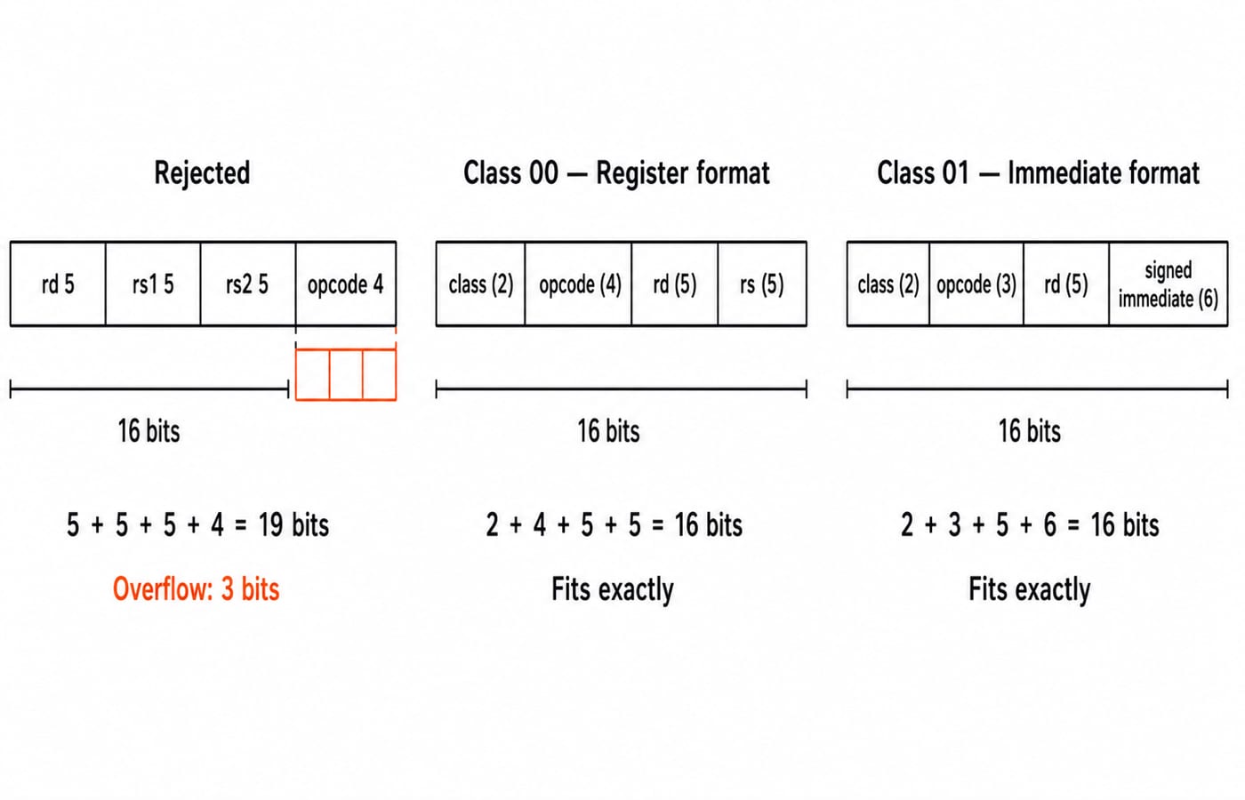
Three registers need 3 x 5 = 15 bits. A four-bit opcode makes 19; adding a two-bit class makes 21. It cannot fit 16 bits.
Our register format is class 00 | opcode 4 bits | rd 5 bits | rs 5 bits. Its budget is 2 + 4 + 5 + 5 = 16. ADD rd, rs means rd <- rd + rs, so the destination is also the first source. Its opcode field permits 2^4 = 16 choices.
The immediate format is class 01 | opcode 3 bits | rd 5 bits | immediate 6 bits. Its budget is 2 + 3 + 5 + 6 = 16. It permits 2^3 = 8 opcode choices and signed immediates from -32 through 31.
Classes 10 and 11 remain reserved and unspecified. Opcode capacity is format-local, so 16 + 8 does not define a complete 24-operation ISA.
4. ISA worked example: encode and execute ADDI R13, -7
Let the immediate-format opcode table assign ADDI = 010. Keep encoding, decoding, and execution clearly separate throughout.
Encoding
Convert each field:
Class:
01Opcode:
ADDI = 010Register:
R13 = 01101Six-bit immediate:
-7 = 111001
Binary 111001 has unsigned value 57. In six-bit two's complement, 57 - 64 = -7. Concatenating the fields gives:
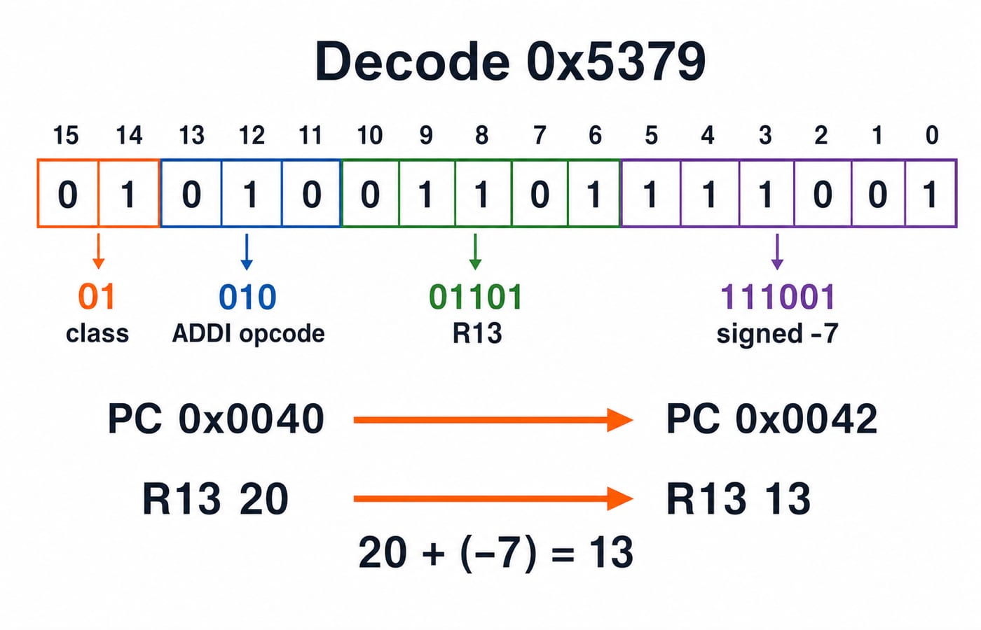
01 | 010 | 01101 | 111001 = 0101001101111001
Group it as 0101 0011 0111 1001. The word is 0x5379.
Reverse decoding
Now decode 0x5379 independently. Bits 15..14 = 01 select the immediate format. Bits 13..11 = 010 select ADDI. Bits 10..6 = 01101 select R13. Bits 5..0 = 111001 sign-extend to -7. Reading that final field as unsigned 57 is wrong because this format defines it as signed.
Execution
Before fetch, PC = 0x0040, memory there contains 0x5379, and R13 = 20. Execution gives R13 = 20 + (-7) = 13. This is not a control transfer, so the two-byte instruction advances PC to 0x0042. All other programmer-visible registers remain unchanged.
5. ISA design styles: what RISC and CISC actually trade
RISC and CISC describe tendencies, not rigid checklists. Typical contrasts include fixed versus variable instruction length, simple versus richer addressing, load/store separation versus operations that may access memory, and easier decode and pipelining versus code density. Real ISAs can mix these traits, so one feature proves neither label. The useful question is which trade-offs a design chooses for its actual workload goals.
Our toy ISA is only RISC-leaning because it has fixed-length words, explicit register operands, and regular formats. It does not model a commercial ISA.
RISC vs CISC Architecture: Control Units, CPI Worked Example and Exam Patterns owns the code-density, control-unit, and CPU-time comparisons. Here, the labels only establish why an ISA style cannot determine implementation or performance: different pipelines may implement 0x5379, but both must produce R13 = 13 and PC = 0x0042.
6. ISA exam patterns: decode fields, count ranges, and predict state
ISA questions can test four defensible tasks:
Field sizing:
32registers require5bits each.Capacity and range: four opcode bits allow
16choices; six signed bits span-32..31.Encoding or decoding: split a word such as
0x5379by its specified format.Architectural state: predict register, PC, or status changes without inventing microarchitectural details.
Use this self-check:
Question | Answer |
|---|---|
Can 16 bits hold three 5-bit register fields plus a 4-bit opcode? | No. It needs |
What does |
|
What follows byte address |
|
GATE CS Exam Preparation places ISA inside the wider syllabus. For each problem, follow the stated format and behaviour instead of assuming an unstated pattern.
7. ISA mistakes: five traps to remove before the exam
Trap | What goes wrong | Correction |
|---|---|---|
Treating ISA and microarchitecture as synonyms | Pipeline details replace architectural behaviour | Any pipeline must leave |
Applying | The two formats are mixed | Class |
Reading a signed immediate as unsigned |
| It is the signed value |
Incrementing a byte-addressed PC by one | A word is confused with one byte |
|
Forgetting two-address semantics | The old destination is ignored |
|
One wording trap remains: “RISC always has exactly one instruction format” is false. Evaluate the stated encoding and behaviour instead of inferring properties from a label.
8. Instruction Set Architecture in the short version
An ISA is the visible contract. Format design budgets bits, decoding maps fields to operands, and execution changes architectural state. The audit line is 0x5379 -> ADDI R13, -7 -> R13: 20 to 13, PC: 0x0040 to 0x0042.
If the design had 16 registers, each register field would need four bits. A classless three-address format with a four-bit opcode would fit exactly: 4 + 4 + 4 + 4 = 16. The trade-off is fewer registers and no class bits. For a sequenced COA and wider GATE study path, continue with GATE Guidance by Sanchit Sir.
Keep learning
Instruction Set Architecture MCQs: 12 Solved ISA Design Questions
Work through 12 ISA questions with teacher-led reasoning, exact field-width calculations and a practical checklist for avoiding common traps.
Updated 3 Aug 20267 min read53 viewsComputer Organization MCQs
Computer Instruction Explained: Format, Instruction Cycle and a 16-Bit Worked Example
Decode an illustrative 16-bit load instruction, calculate its effective address, trace fetch through write-back, and learn the errors that change answers.
Updated 25 Aug 20265 min read62 viewsComputer Organization & Architecture

Bit Stuffing Algorithm: Worked Encoding, De-stuffing and Exam Traps
Learn bit stuffing from the framing problem through a complete 21-bit sender and receiver trace. Calculate inserted bits, lengths and efficiency without losing original data.
Updated 16 Sep 20266 min read51 viewsComputer Networks

Instruction Structure MCQs: 12 Solved Questions on Opcodes, Address Formats and Bit Allocation
Practise instruction formats through 12 solved MCQs. Start with opcode and address-count basics, then work through accumulator code and full encoding numericals.
Updated 29 Oct 20268 min readComputer Organization MCQs