Network Hardware Basics for GATE CS: Devices, OSI Layers, and Collision Domain Counting
Stop mixing up hubs, switches, and routers. Learn the device layers, domain-counting rules, transmission media, and a worked topology for GATE and interviews.
KnowledgeGate Team
Exam prep & CS education
Updated 13 Aug 20266 min read
Hub, switch, and router questions look easy until a topology asks for collision and broadcast domains. Solve them using two facts: the highest OSI layer at which each device makes a decision, and the domain it splits. A hub keeps every attached host in one collision domain, a switch gives each used port its own, and only the router also stops an ordinary broadcast.
The hardware map: what sits where in a network
Network hardware has two buckets. Connecting devices include the NIC, repeater, hub, bridge, switch, router, gateway, and modem. Transmission media include guided twisted pair, coaxial cable, and optical fibre, plus unguided radio, microwave, and infrared.
Define a device by its highest decision layer. A repeater regenerates bits at Layer 1, a switch reads MAC addresses at Layer 2, and a router reads IP addresses at Layer 3. Above Layer 3 sit the transport and application layers, set side by side in OSI vs TCP/IP Model for GATE: Which Layer Does What, with PYQ Traps.
Device by device: layer, intelligence, and forwarding
Domain counts assume the standard exam topology without VLANs. Each device sits at its highest decision layer, which is the layer whose addresses it actually reads.
Device | OSI layer | What it looks at or does | Collision domains | Broadcast domains |
|---|---|---|---|---|
NIC | Layer 2 | Has the 48-bit MAC address burned in and provides the host's network entry point | Belongs to the connected segment | Does not split them |
Repeater | Layer 1 | Regenerates a weak signal without filtering | Extends one shared domain | Does not split them |
Hub | Layer 1 | Acts as a multiport repeater and floods every bit to every port | One across all ports | One across all ports |
Bridge | Layer 2 | Learns MAC addresses and filters traffic, usually across two or a few ports | Each used port is separate | Does not split them |
Switch | Layer 2 | Learns MAC addresses and forwards frames per port, normally in full duplex | Every used port is separate | One across the switch |
Router | Layer 3 | Reads destination IP addresses, forwards packets, and does not forward ordinary broadcasts | Each interface is separate | Each interface is separate |
Gateway | Up to Layer 7 | Translates between dissimilar protocols in the classic textbook sense | Depends on its implementation | Depends on its implementation |
Modem | Layer 1 | Modulates and demodulates, converting digital signals to analogue and back | Does not split the physical segment | Does not split them |
A bridge and a switch both work at Layer 2. A switch is effectively a multiport bridge with hardware-based forwarding.
Collision domains vs broadcast domains: two counting rules
A collision domain is a segment where simultaneous transmissions can interfere on shared media. A broadcast domain is the set of devices that receive a Layer 2 broadcast. Apply two rules:
For collisions, Layer 1 extends and Layer 2 or above splits. A hub or repeater keeps attached devices in one shared collision domain. A bridge, switch, or router creates a separate collision domain on each used port or interface.
For broadcasts, the router is the boundary. Hubs, bridges, and switches forward broadcasts within the standard non-VLAN topology. A router does not forward an ordinary Layer 2 broadcast from one interface to another.
Count each used switch or router port as a collision segment, but collapse a hub and its attachments into one. For broadcasts, remove the router mentally and count the isolated sides.
Worked example: a hub, switch, and router topology
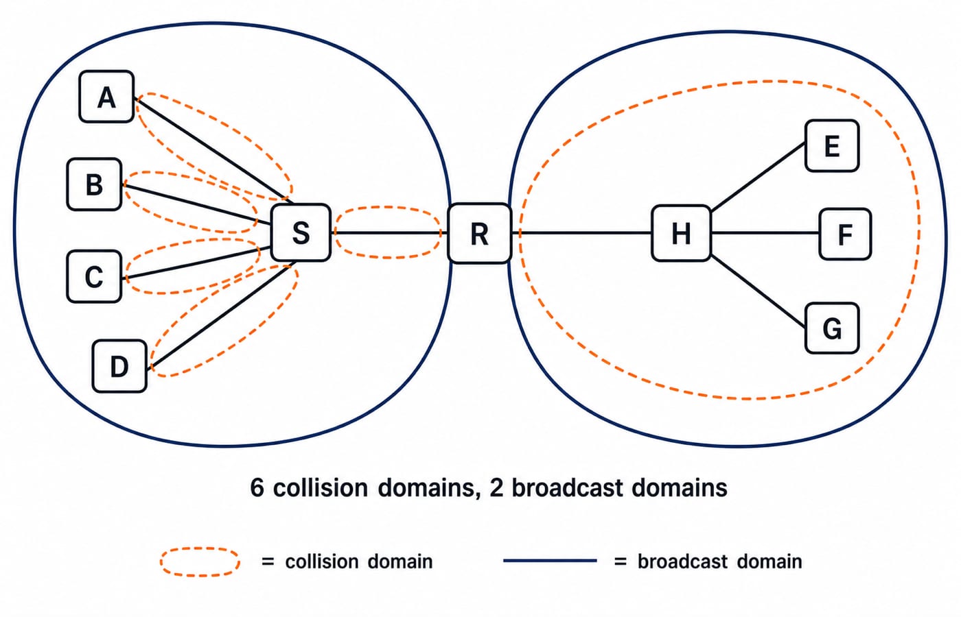
Router R has two interfaces. The first connects to switch S, where hosts A, B, C, and D use four ports and a fifth uplinks to R. The second connects to hub H, where hosts E, F, and G use three ports and a fourth connects to R.
Count collision domains first.
The switch has five used links: S-A, S-B, S-C, S-D, and S-R. Each port separates collisions, giving 5 collision domains.
The hub, E, F, G, and H-R form one shared segment, giving 1 collision domain.
Therefore, total collision domains = switch side + hub side = 5 + 1 = 6.
For broadcasts, R separates its interfaces. The switch side gives one domain and the hub side gives another: 1 + 1 = 2.
The answer is 6 collision domains and 2 broadcast domains. Check it by seeing five independent left links, one shared right segment, and two LANs after removing R.
Replace H with switch S2. The right side now has S2-E, S2-F, S2-G, and S2-R, giving 4 collision domains. The total becomes 5 + 4 = 9 collision domains. R still separates two LANs, so broadcast domains remain 2. A switch multiplies collision domains, while the router boundary controls broadcast domains here.
Transmission media in exam terms
For textbook comparisons, guided-media bandwidth and cost usually rise from twisted pair to coaxial cable to optical fibre.
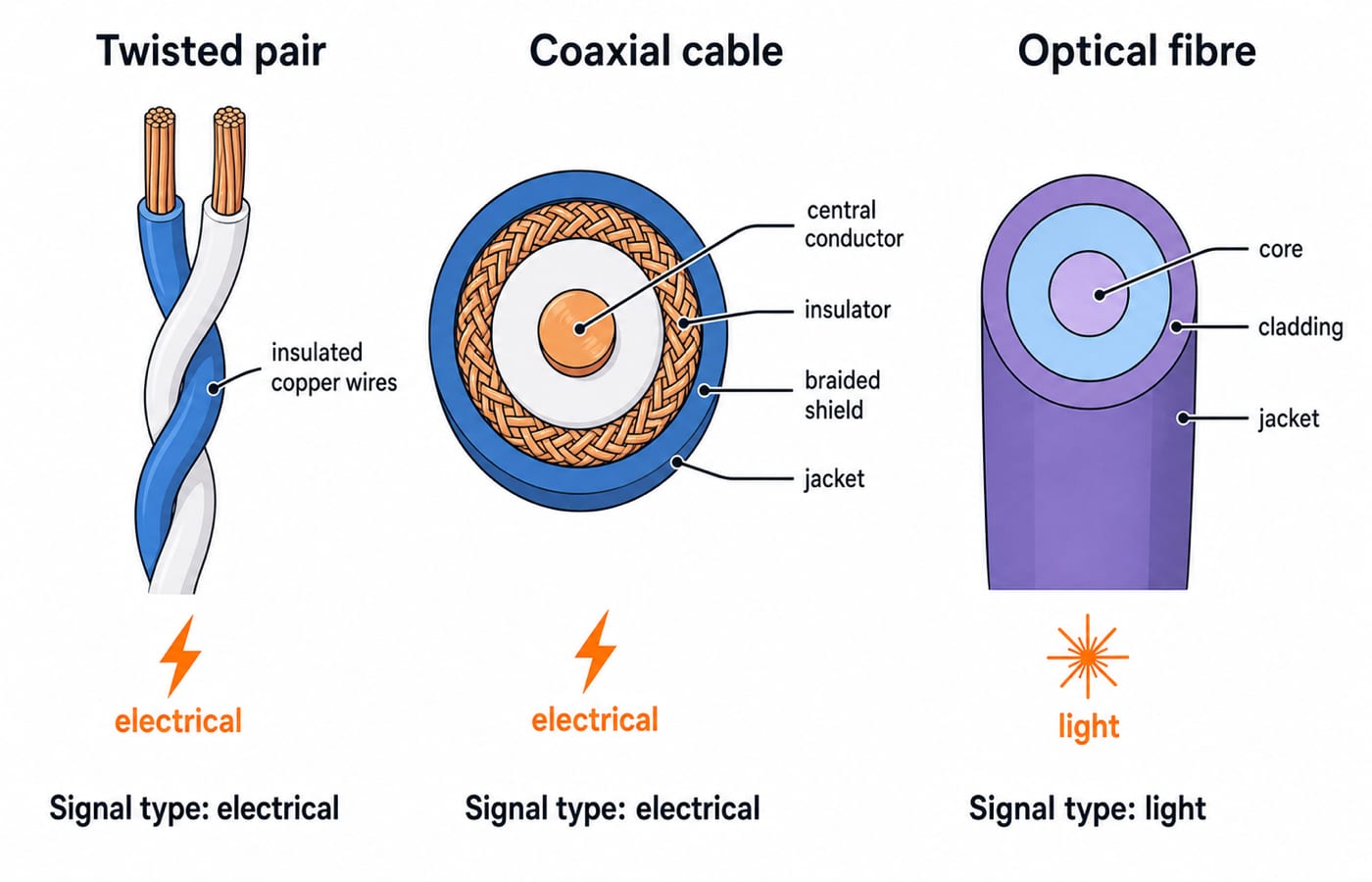
Twisted pair: UTP or STP copper wires twisted together, inexpensive and common in short Ethernet LAN runs.
Coaxial cable: a central conductor, insulation, and braided shield. Its shielding is better than ordinary twisted pair, and it appears in cable television and older networks.
Optical fibre: a core and cladding carry light. It offers the highest bandwidth, longest distances, and immunity to electromagnetic interference.
Unguided media send signals through air. Radio is omnidirectional and can penetrate walls. Microwave needs line of sight and suits long-haul links. Infrared is short range and cannot cross walls, a common one-line question.
Against copper, fibre provides more bandwidth, lower attenuation with wider repeater spacing, and EMI immunity. Keep the comparison qualitative unless a question supplies values.
Traps that cost marks
Saying a switch separates broadcast domains. This confuses collision control with broadcast forwarding. In a standard topology without VLANs, a switch separates collision domains, not broadcast domains.
Counting every hub port separately. A hub repeats bits to all ports, so the hub and its attached links form one shared collision domain.
Forgetting the uplink. S-R is a used switch port and therefore another collision domain. That is why the worked switch side contributes five, not four.
Placing the NIC at Layer 1 because it is hardware. The NIC carries a MAC address and is treated as a Layer 2 device in these questions.
Putting bridges and switches at different layers. Both operate at Layer 2. Their practical differences include port count and switching implementation.
How GATE and interviews test hardware basics
GATE frames this area through device-to-layer matching, media properties, and domain counting, sometimes within a larger topology. The syllabus and paper pattern for each cycle are fixed by the organising institute's brochure, so confirm the current wording on the official GATE 2027 site run by IIT Madras.
In placement interviews, “hub vs switch vs router” is a standard warm-up. Name the layers, the domains each device splits, and one example. Continue the router side with Routing Algorithms: distance vector vs link state, with a worked Dijkstra.
The short version and next step
Identify a device by its highest decision layer. Layer 1 extends collision domains, Layer 2 splits them per used port, and Layer 3 routers also split broadcast domains. The worked answer is 6 collision domains and 2 broadcast domains.
Use GATE CS Subject Weightage to connect this topic with the other subject pillars. For interview-side coverage, study CS Fundamentals for Placements by Sanchit Sir. Then use the GATE Test Series to practise domain counting under time pressure.
Keep learning
Computer Networks Hardware Basics: Devices, Domains and Worked Examples
Learn what hubs, switches, routers, gateways and access points actually do, then count network domains and trace frames through a two-LAN topology.
Updated 6 Oct 20266 min readComputer Networks
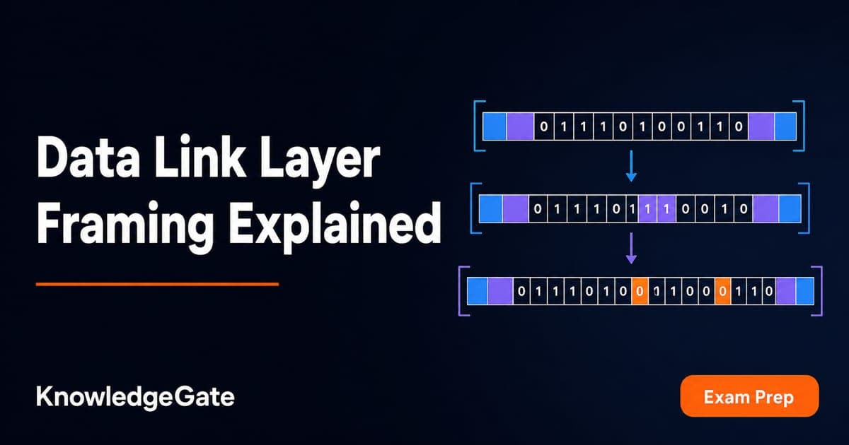
Data Link Layer Framing Explained: Byte Stuffing, Bit Stuffing and a Cross-Concept Numerical
Frame one four-byte payload in two ways, decode it, and then reuse the verified frame sizes in link-load and Stop-and-Wait calculations.
Updated 1 Oct 20266 min readComputer Networks
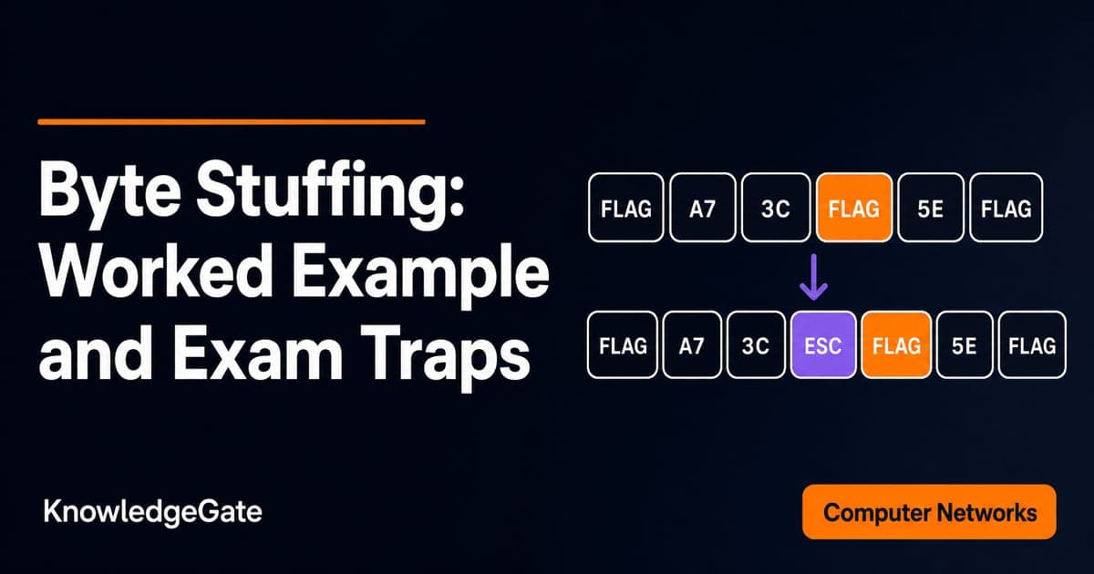
Byte Stuffing in Computer Networks: Worked Framing Example and Exam Traps
Learn a precise byte-stuffing convention, trace a payload containing both FLAG and ESC, reverse it safely, and calculate frame overhead and transmission time.
Updated 26 Sep 20266 min readComputer Networks
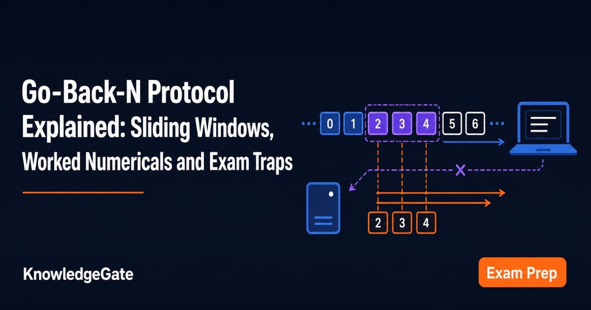
Go-Back-N Protocol Explained: Sliding Windows, Worked Numericals and Exam Traps
Trace Go-Back-N through a lost frame, calculate its legal window and link utilisation, and avoid the ACK and wrap-around traps that spoil numericals.
Updated 24 Sep 20266 min readComputer Networks