

Ethernet Frame Format Explained: Preamble, SFD, Field Sizes and Worked Calculations
Learn exactly what the 64-byte Ethernet minimum includes, how preamble and SFD appear on the wire, and how to calculate padding and transmission time.
KnowledgeGate Team
Exam prep & CS education
Updated 19 Nov 20265 min read
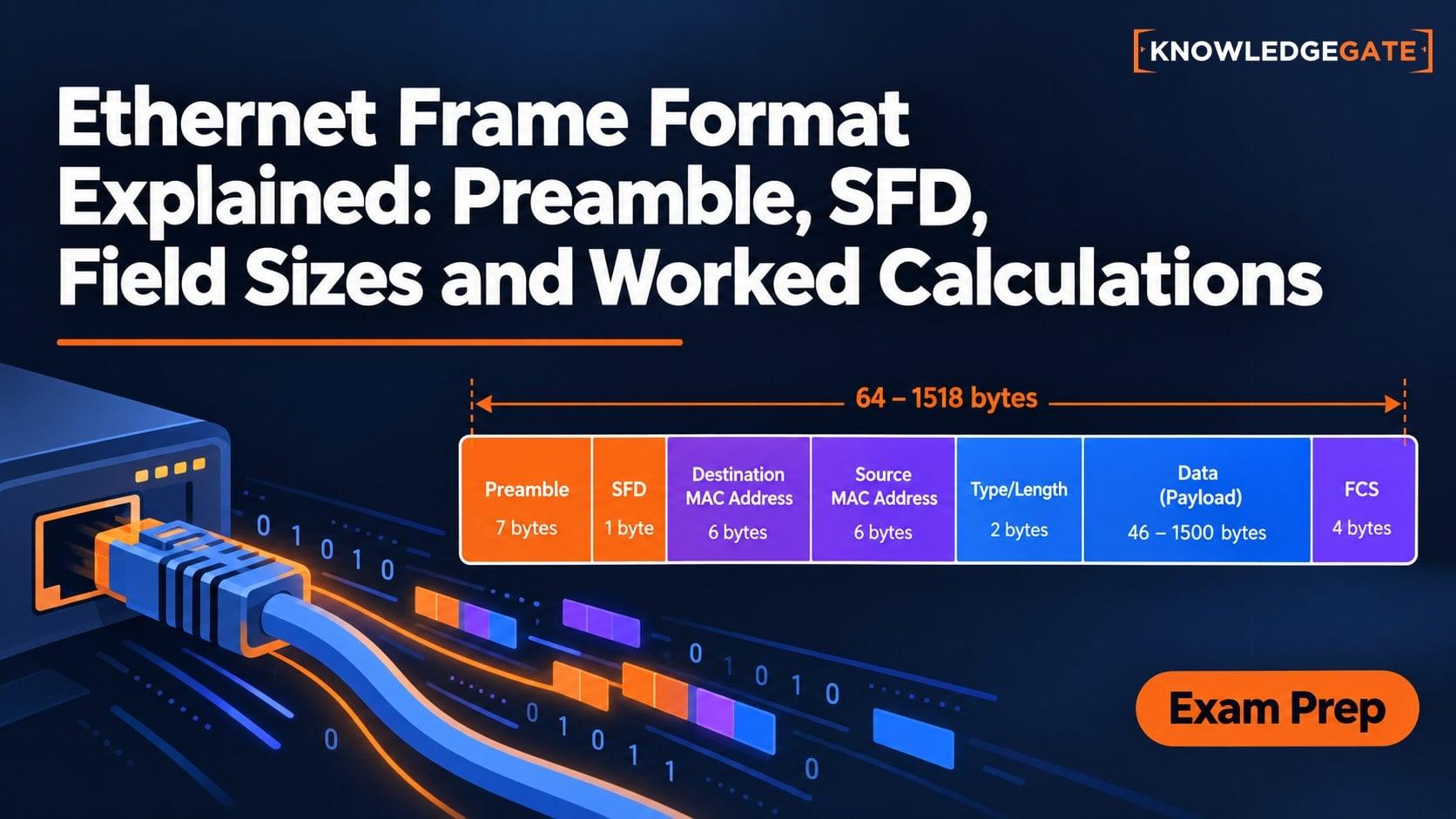
The counting mistake is what makes many Ethernet questions look harder than they are. A diagram may put the preamble, SFD, MAC frame and interpacket gap in one row, but the 64-byte minimum and 1,518-byte maximum for untagged Ethernet II do not count every item in that row. The 64-byte minimum and 1,518-byte maximum for untagged Ethernet II apply to the MAC frame, which runs from Destination Address through FCS; preamble, SFD and interpacket gap are separate. For the wider subject route, use CS Fundamentals for Exams & Placements.
Ethernet frame format: first decide what is being counted
Keep three nested quantities separate:
The MAC frame runs from Destination Address through FCS.
The transmitted sequence has 7 preamble bytes and 1 SFD byte before the MAC frame.
A 96-bit-time interpacket gap follows. It is required idle time, not a frame field and not 12 transmitted data bytes.
For untagged Ethernet II, Destination through FCS is 64 to 1,518 bytes, with 46 to 1,500 bytes of Data plus Pad. Preamble through FCS therefore takes 72 to 1,526 byte-times. The minimum start-to-next-start interval, including the gap, is 84 byte-times.
An IP packet sits inside the Ethernet Data field. The common 1,500-byte MTU limits that payload, not the complete frame. Preamble, SFD and the gap are link overhead. IP Addressing and Subnetting Explained continues at the Network Layer, while TCP vs UDP: Transport Layer Explained covers the layer carried inside IP.
Ethernet preamble and SFD: how the receiver finds the first frame bit
In ordinary hexadecimal and MSB-first binary, each preamble octet is 0x55 = 01010101; SFD is 0xD5 = 11010101. Ethernet sends each octet least-significant bit first, making their time-ordered wire patterns 10101010 and 10101011.
Preamble's repeated transitions let the receiver recover and align its bit clock. SFD means Start Frame Delimiter and is one byte. It ends in consecutive 11 bits on the wire, breaks the alternation, and marks Destination Address as the next octet.
Both are transmitted, but neither enters the 64-byte minimum or FCS calculation. They are not an 8-byte MAC header.
Ethernet frame fields from Destination Address to FCS
Field | Size in the untagged example | Purpose | Included in 64-1,518 bytes? |
|---|---|---|---|
Preamble | 7 bytes | Clock synchronisation | No |
SFD | 1 byte | Frame boundary | No |
Destination Address | 6 bytes | Receiver or group address | Yes |
Source Address | 6 bytes | Sender address | Yes |
EtherType | 2 bytes | Upper-layer protocol | Yes |
Data plus Pad | 46-1,500 bytes | Carried packet plus any minimum-length padding | Yes |
FCS | 4 bytes | CRC-based error detection | Yes |
Interpacket Gap | 12 byte-times | Recovery and spacing before the next frame | No |
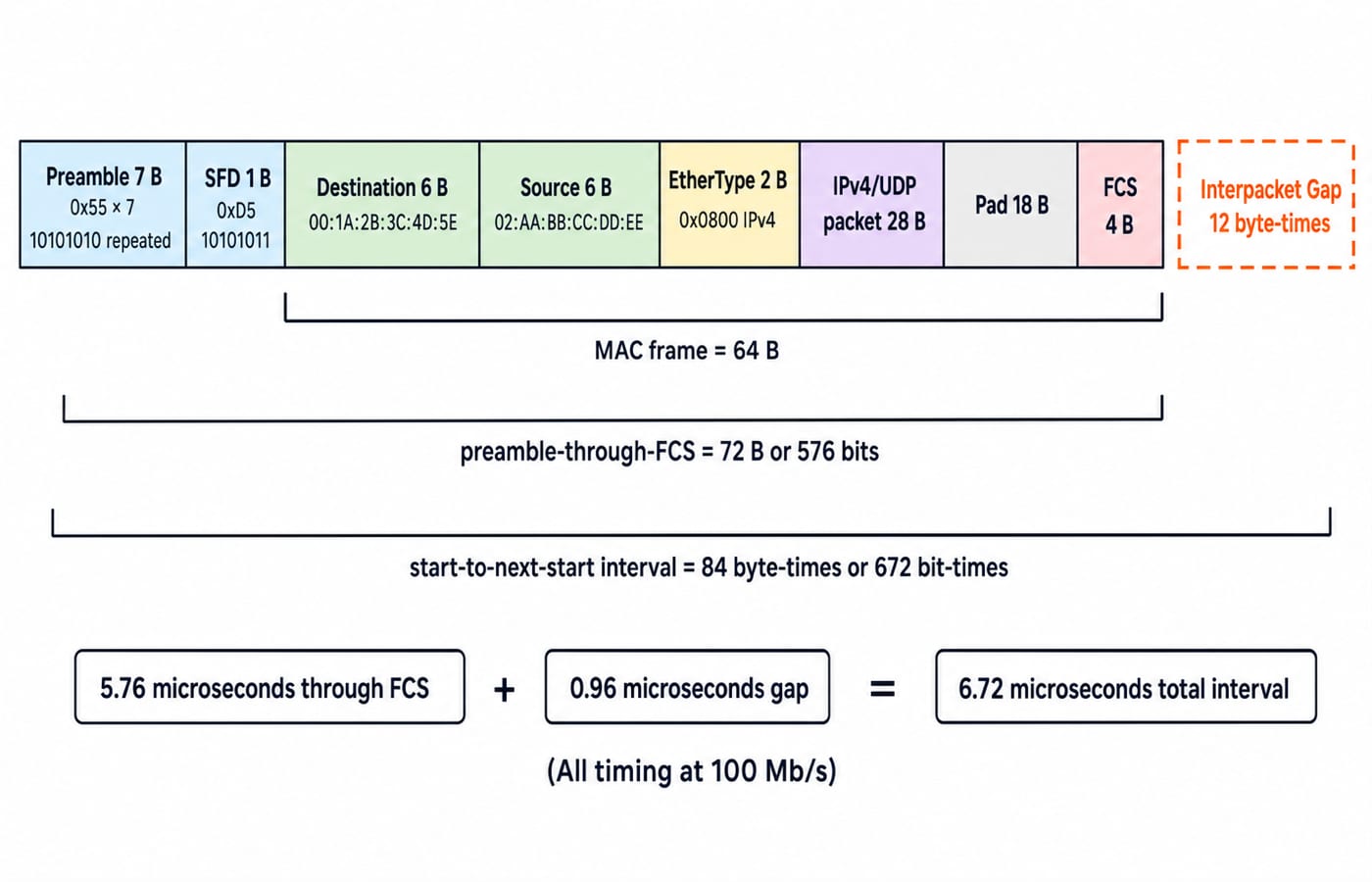
Our first example uses Destination 00:1A:2B:3C:4D:5E, Source 02:AA:BB:CC:DD:EE, and EtherType 0x0800 for IPv4. FCS covers Destination, Source, EtherType, Data and Pad. It detects corruption but neither repairs the frame nor guarantees retransmission.
An IEEE 802.1Q VLAN tag adds 4 bytes between Source and the original EtherType. Our untagged examples retain the 14-byte header and 1,518-byte maximum.
Ethernet minimum-frame worked example: padding a 28-byte IP packet
The frame carries a 28-byte IPv4/UDP packet: a 20-byte IPv4 header and 8-byte UDP header, with no UDP data. It uses the values above. Required padding is:
46 - 28 = 18 bytes
Now sum the MAC frame:
6 + 6 + 2 + 28 + 18 + 4 = 64 bytes
Preamble and SFD give 64 + 7 + 1 = 72 bytes = 576 bits through FCS. The gap gives 72 + 12 = 84 byte-times = 672 bit-times start to start.
At 100 Mb/s, through-FCS time is 576 / (100 x 10^6) = 5.76 microseconds. The gap is 96 / (100 x 10^6) = 0.96 microseconds, so the earliest next start is 6.72 microseconds after the first preamble bit. Thus 64 bytes, 72 bytes and 84 byte-times answer three different boundaries.
Ethernet on-wire-time worked example: a 1,000-byte payload at 1 Gb/s
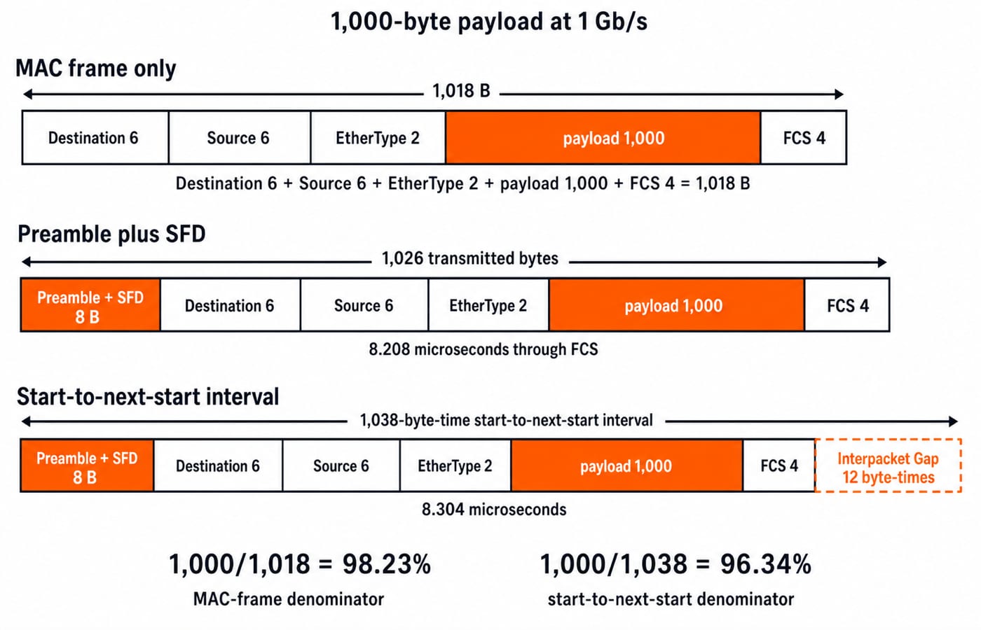
An untagged Ethernet II frame now carries a 1,000-byte IP packet. It needs no padding.
MAC frame:
6 + 6 + 2 + 1,000 + 4 = 1,018 bytesPreamble through FCS:
1,018 + 8 = 1,026 transmitted bytesStart to earliest next start:
1,026 + 12 = 1,038 byte-times
At 1 Gb/s, through-FCS time is 1,026 x 8 / 10^9 = 8.208 microseconds. With the gap, start-to-next-start time is 1,038 x 8 / 10^9 = 8.304 microseconds. The gap remains link time, not frame bytes.
Payload divided by MAC-frame bytes is 1,000 / 1,018 = 98.23%. Payload divided by the complete start-to-next-start budget is 1,000 / 1,038 = 96.34%. Always name the denominator.
Ethernet frame questions: a reliable exam-solving order
Use this sequence:
Identify whether the frame is untagged or VLAN-tagged.
Underline whether “frame” starts at Destination, or whether the question asks for actual wire time.
For the untagged case, calculate Data plus Pad as
max(given payload, 46).Add the 14-byte Destination-through-EtherType header and 4-byte FCS.
Add 8 preamble/SFD bytes only for transmitted-through-FCS time.
Add 96 bit-times only for start-to-next-start timing.
Typical tasks include labelling fields, distinguishing preamble from SFD, decoding 0x0800, finding padding, checking FCS coverage, calculating serialisation time, and comparing payload ratios.
Check the boundaries: a 46-byte payload gives 14 + 46 + 4 = 64 bytes with no pad. A 1,500-byte payload gives 1,518 bytes, or 1,526 transmitted bytes with preamble/SFD. For the broader Ethernet map, Ethernet in the Data Link Layer: Frame Format, CSMA/CD, and Worked GATE Examples covers CSMA/CD, backoff, switching and collision domains; frame-format problems instead turn on boundaries, padding and on-wire timing.
Ethernet frame-format traps and their corrections
Preamble/SFD inside the minimum: This makes 72 bytes the MAC-frame size. Bracket Destination through FCS first.
Gap counted as bytes: It is 96 bit-times of idle spacing, not transmitted frame data.
Short packet accepted as a short frame:
6 + 6 + 2 + 28 + 4 = 46 bytesomits padding. Raise Data plus Pad to 46 bytes first.SFD credited with clock recovery: Preamble supplies the transitions; SFD identifies the boundary.
FCS said to cover preamble or repair errors: It covers Destination through Data/Pad. A failed frame is rejected, not repaired.
Untagged maximum used with a VLAN tag: Write and sum the named fields.
Ethernet frame format: the short version and next step
The durable count is 7 + 1 setup bytes, a 6 + 6 + 2 untagged Ethernet II header, 46 to 1,500 bytes of Data plus Pad, and 4 bytes of FCS. The gap is a separate 96 bit-times. The 64-to-1,518-byte range runs from Destination through FCS.
For a self-test, replace 28 bytes with 40. Pad becomes 46 - 40 = 6 bytes; the MAC frame remains 64 bytes; through-FCS time at 100 Mb/s remains 5.76 microseconds; and start-to-next-start time remains 6.72 microseconds. For structured Computer Networks study including Data Link Layer Ethernet, continue with GATE Guidance by Sanchit Sir.
Keep learning

Ethernet Frame Format MCQs: 12 Solved Preamble and SFD Questions
Choose an answer first, then use the byte count, bit pattern or timing inequality to check it. These 12 solved MCQs cover Ethernet frame boundaries, sizes and MAC addresses.
Updated 2 Nov 20268 min readComputer Networks MCQs

Ethernet in the Data Link Layer: Frame Format, CSMA/CD, and Worked GATE Examples
Build Ethernet from its frame fields upward, then solve collision-window, back-off, efficiency, and domain-counting problems with the reasoning shown.
Updated 15 Aug 20266 min read79 viewsComputer Networks

Computer Instruction Explained: Format, Instruction Cycle and a 16-Bit Worked Example
Decode an illustrative 16-bit load instruction, calculate its effective address, trace fetch through write-back, and learn the errors that change answers.
Updated 25 Aug 20265 min read62 viewsComputer Organization & Architecture

Floating point representation: IEEE 754 format and arithmetic explained
Computers store real numbers in a fixed number of bits, so they cannot store every real number exactly. Floating point packs a huge range of magnitudes into 32 or 64 bits by trading away some precision, and IEEE 754 is the standard almost every processor follows. This topic is a dependable source of encoding and precision questions, all resting on the same field layout and normalization rule.
Updated 30 Oct 20266 min read527 viewsComputer Organization & Architecture