

Network Topologies Explained: Types, Link-Count Formulas and Exam Traps
Learn how physical and logical topology differ, derive link-count formulas, and solve star, ring and full-mesh calculations for eight devices.
KnowledgeGate Team
Exam prep & CS education
Updated 16 Nov 20265 min read
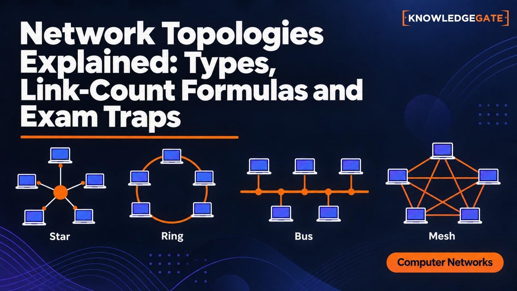
A learner can recognise a star-shaped drawing and still lose marks by counting links, ports, or failure points under the wrong assumptions. Physical arrangement differs from logical communication, and the major topologies have different link-count and failure patterns. In computer science, careful definitions matter as much as formulas.
What a network topology actually describes
A network topology is the arrangement of nodes and links. Physical topology is the actual device and cabling layout. Logical topology is the path followed by frames or data.
Eight computers cabled to one central device form a physical star. An Ethernet hub repeats bits onto a shared medium, while a switch forwards frames over point-to-point computer links. The drawing alone does not settle collision behaviour or logical forwarding.
Topology is not an addressing scheme, transport protocol, or routing algorithm. It shows which connections exist, while route selection chooses an available path.
For the broader survey of layers, switching, and delay, start with Introduction to Computer Networks: Layers, Topologies, Switching and Delay Formulas with Worked Examples. Topology questions then narrow the job to proving link and interface counts, checking degree sums, and stating failure assumptions explicitly.
Bus, star, ring, mesh, tree and hybrid topologies
A point-to-point topology joins two nodes by one dedicated link. A bus attaches devices to a shared backbone. A classic coaxial bus needs a terminator at each end.
In a star, every endpoint connects to a central hub or switch. A ring gives each node two neighbours in a closed cycle. A full mesh links every node pair directly; a partial mesh links only selected pairs.
A tree is a connected, acyclic hierarchy. A hybrid combines structures, such as access stars joined by a backbone.
There is no universal best topology. A star supports easy expansion and branch isolation but depends on its centre. A mesh offers alternate paths at the cost of more cabling and interfaces. A bus depends on its backbone, while a high-level tree failure can remove a branch. The choice depends on scale, redundancy, distance, and budget.
Link and port formulas that exam questions expect
For n end devices in a star, one device-to-centre link per device gives n links and n used centre ports.
In a simple ring, every node has two neighbours. Its degree sum is 2n; since each link contributes two, it has 2n/2 = n links and two interfaces per node.
In a full mesh, each node connects to n - 1 others. The count n(n - 1) includes both A to B and B to A for one link, so divide by two:
Full-mesh links = n(n - 1)/2
Each mesh node needs n - 1 direct-link interfaces.
The tree rule requires a connected, acyclic network: V total vertices give V - 1 edges. V includes internal switches or routers, so eight end devices do not automatically mean seven links.
A bus has no universal n - 1 rule. A question may count the backbone, drops, segments, connectors, or interfaces differently. Identify links, cable runs, ports, or link endpoints before calculating.
Worked example: compare an eight-device network step by step
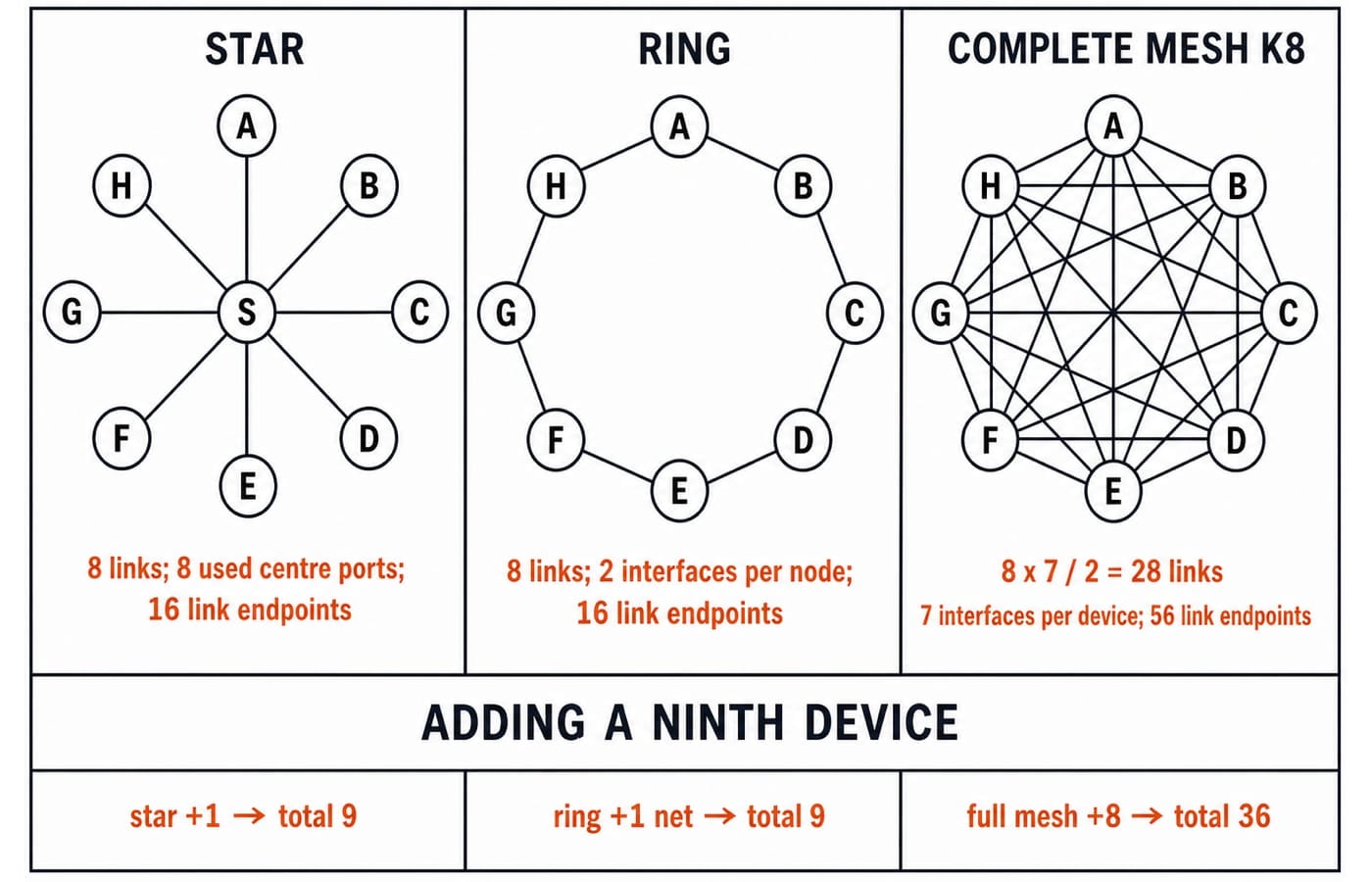
Let the endpoints be A, B, C, D, E, F, G, H, so n = 8.
For a star with centre S, the links are SA, SB, SC, SD, SE, SF, SG, SH.
Number of links:
n = 8.Used ports at
S:8.Link endpoints across both ends:
2 x 8 = 16.
For the simple ring, use AB, BC, CD, DE, EF, FG, GH, HA.
Number of links:
n = 8.Interfaces at each endpoint:
2.Total link endpoints:
8 x 2 = 16.
For the full mesh:
Links:
8(8 - 1)/2 = 8 x 7/2 = 28.Direct-link interfaces per device:
8 - 1 = 7.Total link endpoints:
2 x 28 = 56.Degree-sum check:
8 x 7 = 56 = 2E, soE = 56/2 = 28.
Add device I. The star reaches 9 links, so the increment is 1. Replacing one ring edge with two gives 9 links, also +1. The mesh reaches 9 x 8/2 = 36, so it adds 36 - 28 = 8. A classic bus with eight drops needs two terminators, but n alone gives neither cable length nor segment count.
Failure behaviour and redundancy under stated assumptions
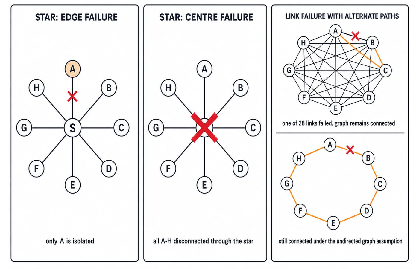
In the star, failure of SA isolates only A. Failure of centre S stops communication through the star for all eight endpoints.
Full mesh K8 has edge connectivity 7. Any set of at most 6 failed links leaves it connected, while seven failures can isolate one device by removing its incident links.
Ring behaviour depends on the model. Removing one edge from an undirected eight-node cycle leaves a connected path. In simple unidirectional token passing, one break can stop circulation without bypass or recovery. Always state the assumption.
A classic bus can be partitioned by a backbone break, and incorrect termination can cause reflections. A failed higher-level tree link disconnects its descendants. Compare fault isolation and redundancy without declaring an absolute winner.
How exams turn topology concepts into questions
Questions may ask for links or ports, identify a topology from node degree or its centre, test a specified failure, or contrast physical and logical topology.
Use this 20-second routine:
Underline exactly what is being counted.
Write the topology and failure assumptions.
Choose the formula before substituting
n.Check the result with
sum of degrees = 2Ewhere appropriate.
For the mesh, 8 x 7 = 56, then 56/2 = 28. This catches the mistake of reporting ordered endpoint connections as physical links.
After the concept pass, practise Network Topologies in CS Fundamentals for Exams & Placements. For a structured route through the wider syllabus, use GATE Guidance by Sanchit Sir.
Common traps, the short version and what to study next
Topology | Defining structure | Link-count rule | Shared or central failure risk | Expansion implication |
|---|---|---|---|---|
Bus | Shared backbone | Depends on counting convention | Backbone or termination can affect many devices | A drop changes the shared medium |
Star | Endpoints connect to a centre |
| Centre affects all; branch affects one | Add one link and centre port |
Ring | One cycle |
| Depends on direction and recovery | Replace one link with two |
Full mesh | Every pair linked |
| Alternate paths; minimum cut | New node needs |
Tree | Connected and acyclic |
| High-level failure removes a branch | Preserve acyclic connectivity |
Hybrid | Combined structures | No universal formula | Depends on design | Follow each component topology |
Remember the traps: full mesh is not partial mesh; ordered pairs double-count links; hub and switch stars differ logically; ring recovery varies; tree counts include internal devices; bus counts need a convention.
Recalculate the eight-to-nine-device example unaided. Next study IP Addressing and Subnetting Explained, then TCP versus UDP. For networks alongside DBMS and operating systems, use the placement-focused CS Fundamentals for Placements by Sanchit Sir. GATE aspirants can follow the broader path above.
Keep learning

Introduction to Computer Networks: Layers, Topologies, Switching and Delay Formulas with Worked Examples
Build the Computer Networks foundation that later CN topics assume, including layer models, topology maths, switching choices and an end-to-end delay calculation.
Updated 17 Aug 20266 min read121 viewsComputer Networks

Network Topology MCQs: 12 Solved PYQs with Answers and Explanations
Solve 12 network topology PYQs and learn how physical cues, failure behaviour, cabling needs and pair counting reveal the correct answer.
Updated 29 Oct 20267 min read208 viewsComputer Networks MCQs
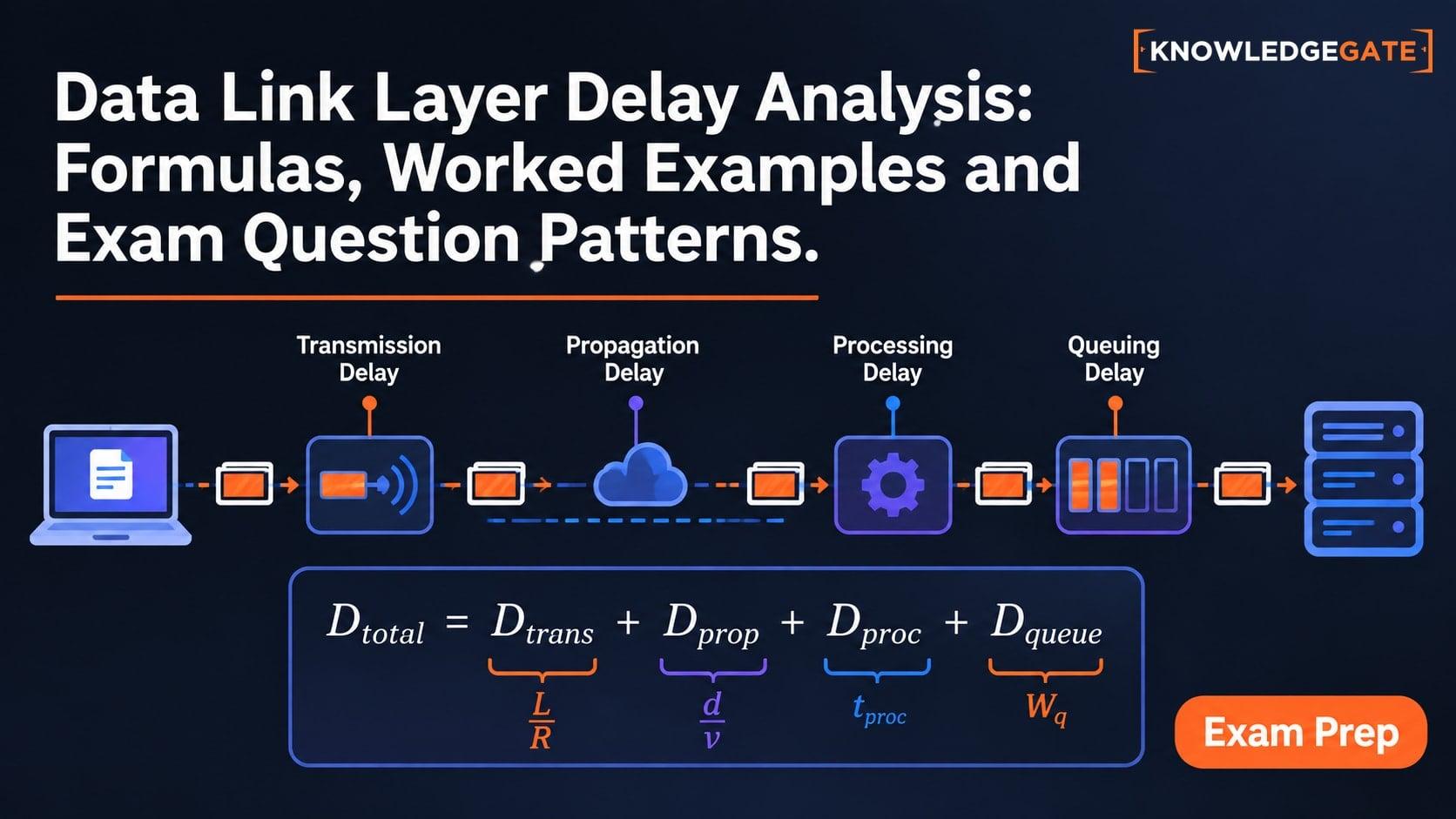
Data Link Layer Delay Analysis: Formulas, Worked Examples and Exam Question Patterns
Learn to separate transmission and propagation delay, calculate a complete stop-and-wait cycle, and choose the minimum sliding-window size without unit traps.
Updated 22 Sep 20265 min read75 viewsComputer Networks

Reflexive and Irreflexive Relations: Counts, Properties and Worked Examples
Learn to classify a relation from its diagonal, count the possible relations on an n-element set, and avoid the common confusion between irreflexive and not reflexive.
Updated 17 Nov 20266 min readEngineering Mathematics