

Computer Graphics Basics: From Coordinates to Pixels and Frame-Buffer Bytes
Follow one triangle from object coordinates through matrix transformation and viewport mapping to edge pixels, a 135-byte RGB buffer, and exact byte offsets.
KnowledgeGate Team
Exam prep & CS education
Updated 19 Nov 20265 min read
A learner may know a pixel, matrix, viewport and frame buffer separately, then lose the connection when one primitive passes through them. A graphics problem is a data pipeline; each stage feeds the next. The triangle A=(1,1), B=(3,1), C=(1,2) is transformed and mapped into a 9 x 5 raster; its edge pixels are selected and its exact RGB byte locations are calculated. For CS foundations, see the CS Fundamentals for Exams & Placements.
Read computer graphics basics as one connected pipeline
Use this chain: object coordinates -> world transformation -> viewing window -> viewport mapping -> rasterisation -> frame buffer -> display. Object and world coordinates describe continuous geometry. The window selects a region, viewport mapping produces device coordinates, rasterisation chooses discrete samples, and the frame buffer stores their channel values.
A point is a mathematical location. Lines and polygons are primitives built from points. A pixel is an addressable raster sample. Spatial resolution counts sample positions, colour depth counts bits per pixel, and the frame buffer holds those values. A transformed point is not yet a pixel.
The calculation uses scale 2, translation (1,0), window [0,8] x [0,4], columns 0..8, rows 0..4, 24-bit RGB, and orange (255,128,0).
Declare coordinate and storage conventions before calculating
Use 2D homogeneous column vectors [x,y,1]^T, multiply matrices on the left, and let the rightmost act first. World coordinates have x right and y up. Screen (0,0) is at the top left, with x right and y down. Another source may choose differently, so the convention is part of the data.
The continuous window has x_w in [0,8] and y_w in [0,4]. A 9 x 5 raster has integer coordinates x_p in {0,...,8} and y_p in {0,...,4}. Its boundary spans are therefore 9-1=8 and 5-1=4, not 9 and 5.
For memory, assume packed RGB, 8 bits per channel, R,G,B order, no alpha, padding or compression, top-left row-major storage, and zero-based offsets. Different storage assumptions change the answer.
Worked example, stage 1: scale and translate the triangle
The scale and translation matrices are:
S=[[2,0,0],[0,2,0],[0,0,1]]
T=[[1,0,1],[0,1,0],[0,0,1]]
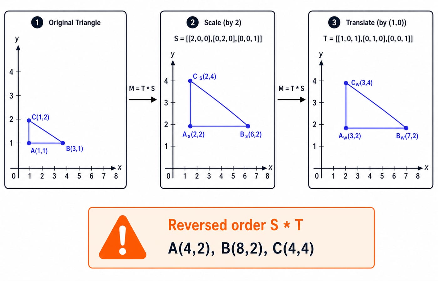
Scaling first and translating second gives M=T*S=[[2,0,1],[0,2,0],[0,0,1]]. Apply it to every vertex:
A_w=M[1,1,1]^T=[3,2,1]^TB_w=M[3,1,1]^T=[7,2,1]^TC_w=M[1,2,1]^T=[3,4,1]^T
Two checks confirm the result. The original horizontal length AB=2 becomes A_wB_w=4, while vertical length AC=1 becomes A_wC_w=2. Both doubled. Translation adds 1 only to each x-coordinate, so it changes position but not length.
Order matters. Reversing the operations gives S*T=[[2,0,2],[0,2,0],[0,0,1]], sending the vertices to A=(4,2), B=(8,2), C=(4,4). These are not the required world coordinates. The Computer Graphics Fundamentals: Applications, Core Components and a Worked Pixel Pipeline article explains the broader applications, components, representation types, and depth testing. In the 9 x 5 trace here, focus on boundary mapping, raster tie-breaking, and exact RGB byte offsets.
Worked example, stage 2: map the window and rasterise the edges
For a top-left screen origin, derive the mapping from the two boundary spans:
x_p=((x_w-0)/(8-0))*(9-1)=x_w
y_p=((4-y_w)/(4-0))*(5-1)=4-y_w
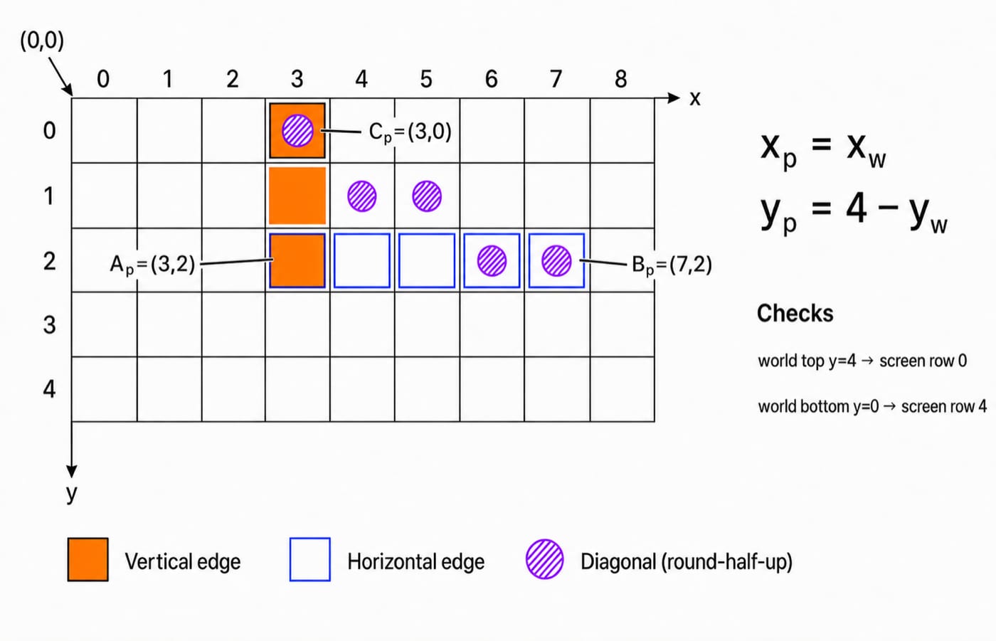
Thus A_w(3,2) -> A_p(3,2), B_w(7,2) -> B_p(7,2), and C_w(3,4) -> C_p(3,0). The y-value flips because world y rises upward while screen row numbers rise downward.
Check the full boundaries before sampling. World x_w=0 maps to column 0 and x_w=8 to column 8. World y_w=4 maps to row 0, while y_w=0 maps to row 4. The complete window therefore stays inside the raster.
Rasterise the three edges next. The vertical edge C_pA_p selects (3,0),(3,1),(3,2). The horizontal edge A_pB_p selects (3,2),(4,2),(5,2),(6,2),(7,2).
For diagonal C_pB_p, evaluate y=0.5x-1.5 at integer x from 3 through 7 and use round half up. The y-values 0,0.5,1,1.5,2 become 0,1,1,2,2, selecting (3,0),(4,1),(5,1),(6,2),(7,2). The exact set depends on the coverage and tie-breaking rule. Another valid rasteriser may choose differently, which is why the rule must accompany the answer.
Worked example, stage 3: calculate frame-buffer size and byte offset
Calculate raw storage with units on every line:
9 x 5 = 45 pixels24 bits/pixel = 3 bytes/pixel45 pixels x 24 bits/pixel = 1080 bits1080 bits / 8 bits/byte = 135 bytes
The format uses 24 bits per pixel, not 24 bits per channel. Each pixel therefore occupies three consecutive bytes.
For B_p=(7,2), the row-major pixel index is 2*9+7=25. Its first byte offset is 25*3=75. If the pixel is orange, RGB(255,128,0), offsets 75,76,77 store FF,80,00 hexadecimal respectively. Number Systems and Base Conversions Explained develops that decimal-to-hexadecimal step.
Finally, (8,4) has index 4*9+8=44, starts at 44*3=132, and occupies bytes 132,133,134. That fits exactly inside 135 bytes with valid offsets 0..134.
Traps that break an otherwise correct graphics solution
Write each trap as cause, wrong result, repair:
Reversing matrix order gives
A=(4,2), not(3,2). Write the operation sequence first.Mixing row and column vectors moves translation. Convert matrices to the declared convention.
Missing y inversion puts
C_w(3,4)on row 4, not row 0. Test both vertical boundaries.Using 9 instead of
9-1sendsx=8past columns0..8. Map boundary to boundary.Treating 24 bits as 24 bytes inflates 135 bytes to 1080 bytes. Convert units.
Omitting
3 bytes/pixelturns pixel index 25 into byte offset 25, not 75. Keep them separate.
“Orange at offset 75” still depends on RGB order, padding, compression and origin. Diagonal y values 0.5 and 1.5 need a tie rule. Write a one-line convention box before you start the arithmetic.
How cross-concept graphics questions are built and checked
Questions ask for a composite matrix, vertex trace, viewport mapping, pixel sequence under a stated rule, raw storage, or byte address. Combined steps let errors propagate.
Use a compact answer table to stop that propagation:
Stage | Values to write | Sanity check |
|---|---|---|
Transform |
| Lengths doubled |
Viewport |
| Boundaries remain |
Raster | Declared round-half-up pixel set | Endpoints included |
Memory |
| Last valid byte is |
To extend the trace into exam-style variants, change one assumption at a time: matrix order, viewport origin, pixel format, or row padding. For UGC NET Computer Science preparation, the NTA UGC NET Paper 2 course includes Computer Graphics in its live curriculum.
Computer graphics basics: the short version and next step
Recall A(1,1) -> scale to (2,2) -> translate to A_w(3,2) -> map to A_p(3,2) -> raster sample -> RGB bytes. Check M=T*S, y_p=4-y_w, 135 bytes, and B starting at byte 75.
For practice, set A_p=(3,2) to RGB(0,64,255). Its index is 2*9+3=21; offset 21*3=63; bytes 63,64,65 hold 00,40,FF.
For a connected, semester-oriented CS route, inspect ZERO TO HERO. Otherwise, redraw both figures and recompute the checks unaided.
Keep learning
Mathematical Representation of Points and Lines in Computer Graphics: From Equations to Pixels
Follow one segment from Cartesian coordinates to line equations, a point projection, a homogeneous intersection and seven selected pixels.
Updated 21 Aug 20266 min readEngineering Mathematics

Ethernet in the Data Link Layer: Frame Format, CSMA/CD, and Worked GATE Examples
Build Ethernet from its frame fields upward, then solve collision-window, back-off, efficiency, and domain-counting problems with the reasoning shown.
Updated 15 Aug 20266 min read79 viewsComputer Networks

Computer Graphics Fundamentals: Applications, Core Components and a Worked Pixel Pipeline
Follow a triangle from object coordinates to a tested screen pixel, then calculate the colour and depth-buffer memory needed to store the result.
Updated 11 Nov 20266 min readComputer Organization & Architecture

Computer Graphics for GATE: Syllabus Status, Weightage Reality and How to Prepare
Computer Graphics is important in a CS degree, but that does not automatically make it a GATE CS subject. See where it is tested, what overlaps with GATE, and how to allocate your study time.
Updated 30 Oct 20265 min readTeaching Recruitment (Computer Science)