

ISRO CS COA Numericals: Cache Mapping, Pipeline Timing and Addressing Modes
Three reusable COA scratchpads turn cache mapping, pipeline penalties and signed addressing-mode displacements into quick, checkable calculations.
KnowledgeGate Team
Exam prep & CS education
Updated 18 Nov 20266 min read
You may be able to define set-associative cache, pipelining and PC-relative addressing, yet still lose time when a numerical hides its target behind units, hexadecimal values or a stall condition. The fix is a reusable scratchpad method: identify the model, label every value, calculate only what is asked, then run a bound check. A cache address split, a pipeline timing comparison and an effective-address table illustrate the method.
Classify the numerical before touching the arithmetic
First decide which input controls each step.
Numerical type | Inputs to identify | Core calculation |
|---|---|---|
Cache | Address width, byte or word addressability, data capacity, block size, associativity |
|
Pipeline | Stage delays, latch overhead, stage count |
|
Addressing mode | Address or signed displacement, field width, PC sampling point, requested EA or operand |
|
Use this scratchpad order:
Convert powers of two and units.
Write the requested output with its unit.
Substitute the labelled values.
Check one range, direction or timing bound.
Keep byte addresses, bytes, cycles and picoseconds visible so no unit changes silently.
Worked cache numerical: split the address and decide the hit
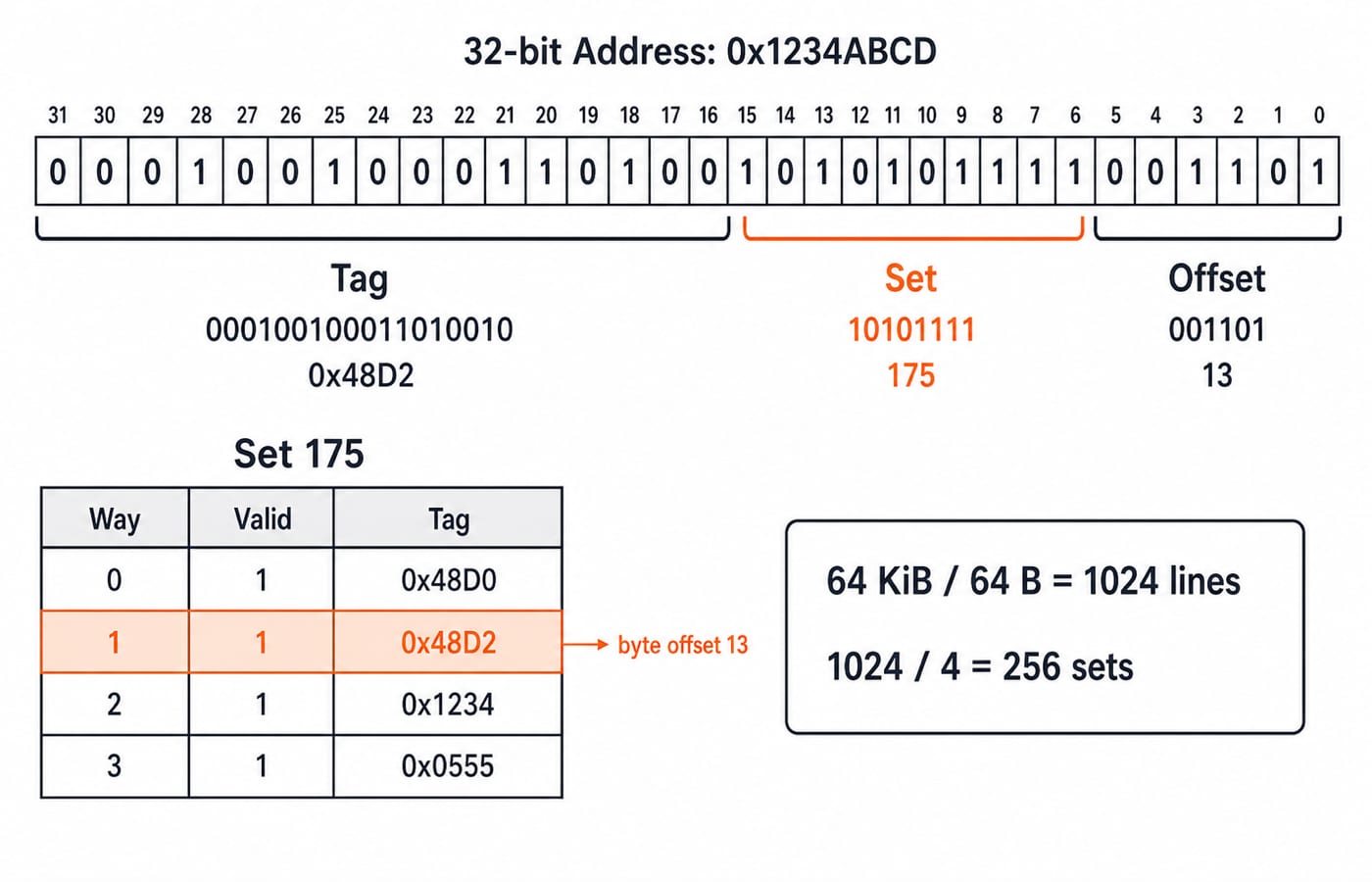
Consider 32-bit byte-addressable memory, a 64 KiB data cache, 64-byte blocks and four-way set associativity.
Convert first:
64 KiB = 2^16 bytes64-byte block = 2^6 bytes, so the offset needs 6 bitslines = 2^16 / 2^6 = 2^10 = 1024sets = 1024 / 4 = 256 = 2^8, so the index needs 8 bitstag bits = 32 - 8 - 6 = 18
Four ways do not require four index bits. Associativity produces 256 sets, and that set count determines the index width.
Now decode 0x1234ABCD. Its 32-bit binary form is:
00010010001101001010101111001101
Splitting it as 18 tag bits, 8 set bits and 6 offset bits gives:
000100100011010010 | 10101111 | 001101
The tag is 0x48D2, or 18,642; the set is 0xAF, or 175; and the byte offset is 0x0D, or 13. Cross-check: floor(0x1234ABCD / 64) = 4,772,527, and 4,772,527 mod 256 = 175.
Set 175 contains valid tags [0x48D0, 0x48D2, 0x1234, 0x0555]. This is a hit in the 0x48D2 way, at byte offset 13. Cache Memory Mapping and Hit Ratio: Solved Examples extends this split into mapping comparisons and hit-ratio calculations.
Worked pipeline numerical: clock, latency, throughput and stalls
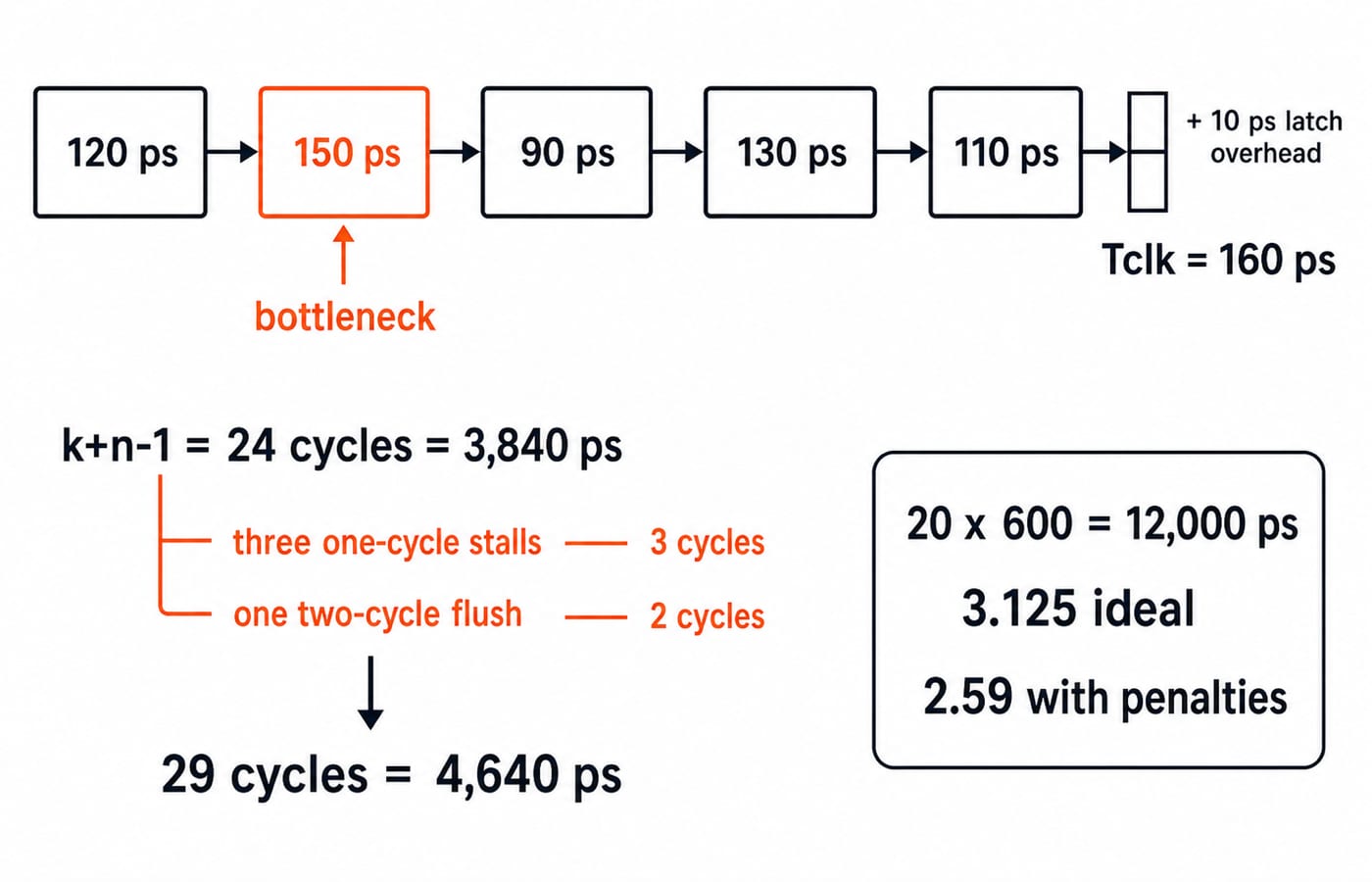
Take a five-stage pipeline with delays [120, 150, 90, 130, 110] ps and 10 ps interstage latch overhead. The slowest stage controls the clock:
Tclk = 150 + 10 = 160 ps
First-instruction latency is 5 x 160 = 800 ps. Once full, the ideal throughput is one completed instruction every 160 ps. Latency and throughput are different metrics.
For 20 instructions, ideal cycles are:
k + n - 1 = 5 + 20 - 1 = 24 cycles
Ideal time is 24 x 160 = 3,840 ps. The non-pipelined reference is a single-cycle design with the same stages and no pipeline-latch overhead. Its cycle is 120 + 150 + 90 + 130 + 110 = 600 ps; 20 instructions take 12,000 ps. Ideal speedup is 12,000 / 3,840 = 3.125, not five.
Add three one-cycle data-hazard stalls and one taken branch with a two-cycle flush. If these five lost cycles do not overlap, actual cycles are 24 + 3 + 2 = 29. Time is 29 x 160 = 4,640 ps; speedup is 12,000 / 4,640 = 2.586..., or about 2.59. Pipelining Basics in Computer Architecture: Clock Cycle, Speedup and Hazard Worked Examples derives finite-batch timing and a cycle-by-cycle load-use trace. This 20-instruction case instead combines an unequal-stage clock, three one-cycle stalls and a two-cycle branch flush.
Worked addressing-modes numerical: separate EA from operand
Use one byte-addressed state. The PC has already advanced to 0x1004; R2 = 0x2000; R3 = 0x0030; a 12-bit displacement is 0xFEC; a separate 16-bit address field is 0x3000; M[0x3000] = 0x4000; and M[0x4000] = 77. The advanced PC removes instruction-start ambiguity.
The 12-bit 0xFEC has its sign bit set. Sign extension gives 0xFEC - 0x1000 = -0x14 = -20.
Mode | Calculation | Result asked for |
|---|---|---|
Immediate | Use the signed field itself | Operand |
Register | Read | Operand |
Base-displacement |
| EA |
PC-relative |
| EA |
Indexed |
| EA |
Direct | Use address field | EA |
Memory-indirect | First read | EA |
Use two operations: calculate EA from the mode, then access memory only if the question asks for the operand. Immediate and register modes supply the operand without an EA lookup.
Three sanity checks that catch errors quickly
Cache: fields must total 32 bits:
18 + 8 + 6 = 32. Set 175 is within 0 to 255, and offset 13 is within 0 to 63.Pipeline:
4,640 psmust exceed3,840 ps, while remaining below12,000 ps. Penalised time below ideal time is impossible.Addressing: a negative displacement must lower its base, so
0x1FEC < 0x2000and0x0FF0 < 0x1004. Adding0x30to0x3000must raise it to0x3030.
Common traps and the replacement idea
For cache questions, do not read 64 KiB as 64,000 bytes, confuse lines with sets, or use log2(ways) as index width. Follow capacity to lines to sets to fields. Total physical cache size including metadata requires a different capacity equation.
For pipelines, do not add all stage delays for the clock, forget latch overhead, use n x k as ideal cycles, or count a penalty in both picoseconds and cycles. Start with k+n-1, add each non-overlapping penalty once, then multiply by Tclk once.
For addressing modes, do not treat immediate data as an address, read 0xFEC as unsigned 4,076, use the instruction's starting address when an advanced PC is supplied, or stop at the pointer location in indirect mode. Label field width, signedness, PC timing, EA and operand.
How to practise this toolkit for ISRO CS
Practise splitting tag, set and offset; timing unequal stages; adding stalls or flushes; and comparing effective addresses. These methods transfer across objective questions. Recruitment-specific details such as the syllabus, dates, marking rules and cutoffs must come from the current ISRO Careers page.
Try a timed three-pass routine. First write 1024 lines -> 256 sets -> 18/8/6. Next write Tclk 160 ps -> 24 ideal cycles -> 29 actual cycles. Finally mark every addressing result as either EA or operand. Then change one input at a time: double the associativity, add one branch-penalty cycle, and reverse the displacement sign. Each new result should still pass the three sanity checks above.
The short version
Divide cache capacity before splitting address bits. Let the slowest pipeline stage set the clock, then add penalties to the cycle count. Sign-extend a displacement before calculating an effective address.
Use the ISRO Scientist/Engineer SC Computer Science course for an exam-focused next step, the GATE Guidance by Sanchit Sir course for broader core-CS revision, or the ISRO Scientist/Engineer CS preparation category as a neutral hub.
Keep learning
Cache Memory Organization in COA: Mapping, Hit Ratio and Worked Examples
Learn cache organization through one 64 KB memory and 1 KB cache example, carried from address fields and mapping to AMAT, writes, replacement and directory size.
Updated 18 Aug 20267 min read64 viewsComputer Organization & Architecture

Instruction Formats and Addressing Modes for GATE: One Cross-Concept COA Problem Solved
Decode one teaching instruction from 0x2E35FFEC, calculate its effective address, read the little-endian value, and trace the result through a five-stage pipeline.
Updated 15 Sep 20266 min readComputer Organization & Architecture
Instruction Formats and Addressing Modes in COA: Complete Guide with Worked Examples
Learn how zero, one, two, and three-address instructions change a program, then solve expanding-opcode and effective-address questions step by step.
Updated 30 Oct 20266 min read72 viewsComputer Organization & Architecture
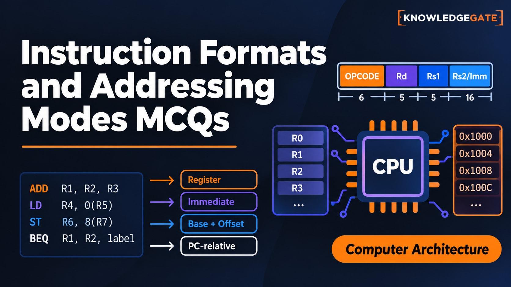
Instruction Formats and Addressing Modes MCQs: 12 Solved Cross-Concept Questions
Solve 12 cross-concept COA questions that connect addressing-mode choices with PC rules, memory references, opcode fields, and byte-aligned instructions.
Updated 29 Oct 20267 min readComputer Organization MCQs