Basic Addressing Modes in Computer Architecture: Worked Effective-Address Examples and Exam Traps
Stop mixing up the instruction field, effective address, and operand. Reuse one machine state to calculate each basic addressing mode step by step.
KnowledgeGate Team
Exam prep & CS education
Updated 20 Sep 20266 min read

Students often memorise addressing-mode names but mix up the instruction field, effective address, and final operand. The fix is to reuse one machine state and follow the data one step at a time, separating the field, EA, operand, and extra memory reads. The GATE CS Exam Preparation hub places this topic inside the broader syllabus.
Addressing modes start with effective address, not a memorised definition
An addressing mode is the rule an instruction uses to locate an operand. A denotes the instruction's address field, R_i a register, PC_after the program counter after instruction fetch, EA the effective address, and M[x] the contents of memory location x.
The decisive distinction is simple: EA is a location, while a memory operand is M[EA]. Immediate mode takes its operand from the instruction, and register mode takes it from a register. Neither needs a data-memory effective address.
For every question, separate three decisions:
What value is encoded in the instruction?
Is an effective address formed?
How many operand-memory reads occur after the instruction has been fetched?
Basic addressing modes and their formulas
Mode | EA rule | Operand source | Extra operand-memory reads | Typical purpose |
|---|---|---|---|---|
Immediate | No EA, | Instruction field | 0 | Constants |
Register | No memory EA, | Register | 0 | Fast register data |
Direct or absolute |
|
| 1 | Fixed memory location |
Memory indirect |
|
| 2 | Pointer stored in memory |
Register indirect |
|
| 1 | Pointer held in a register |
Indexed |
|
| 1 | Arrays and tables |
Base plus displacement |
|
| 1 | Records and stack frames |
PC-relative |
|
| 1 | Nearby control or data reference |
Auto-update register indirect | Old or updated |
| 1 | Sequential traversal |
Assembly syntax and names differ across instruction set architectures. Implied and stack addressing are special cases: the accumulator, operand register, or stack pointer is understood rather than written explicitly. Addressing Modes and Instruction Formats connects mode bits to instruction-width budgets and zero- to three-address trade-offs. Instruction Formats and Addressing Modes in COA extends the format arithmetic through expanding opcodes. Holding the format fixed isolates each basic mode's EA rule, operand source, and extra memory reads.
Addressing modes worked example: compute EA and operand from one machine state
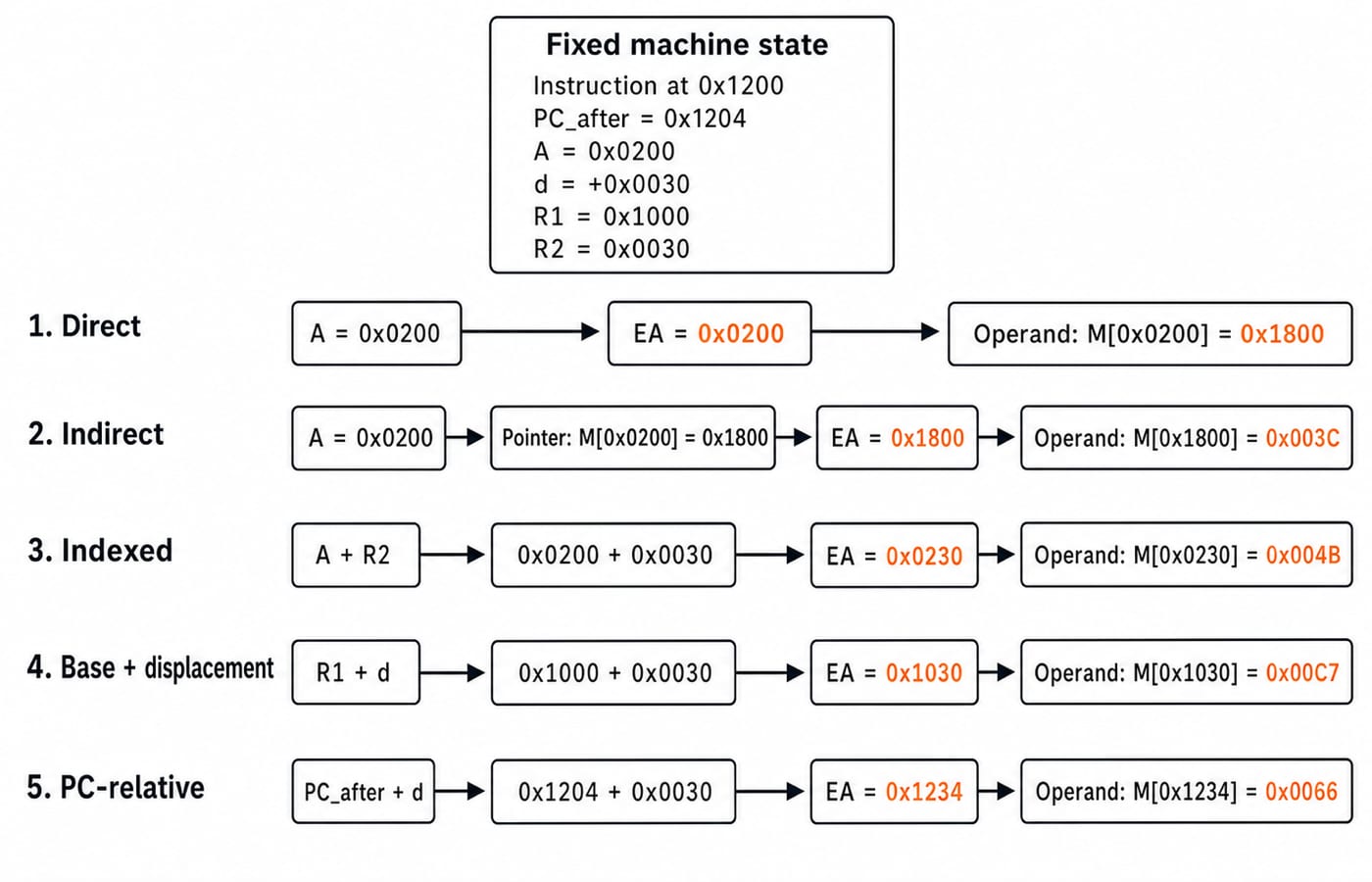
Fix this state. A 4-byte instruction begins at 0x1200, so PC_after=0x1204. Let A=0x0200, d=+0x0030, R1=0x1000, and R2=0x0030. Memory contains:
M[0x0200]=0x1800, M[0x1800]=0x003C, M[0x1000]=0x00A5, M[0x0230]=0x004B, M[0x1030]=0x00C7, and M[0x1234]=0x0066.
Mode | Step-by-step result | EA | Operand |
|---|---|---|---|
Immediate | Read | None |
|
Register using | Read | None |
|
Direct |
|
|
|
Memory indirect | Pointer read |
|
|
Register indirect through |
|
|
|
Indexed |
|
|
|
Base plus displacement |
|
|
|
PC-relative |
|
|
|
Direct and indirect modes reveal the central trap. In direct mode, 0x1800 is the final data. In memory-indirect mode, the same 0x1800 becomes the next address, so another read produces 0x003C.
These read counts exclude instruction fetch. Immediate and register modes need zero extra reads. Direct, register-indirect, indexed, base-relative, and PC-relative modes need one. Memory indirect needs two.
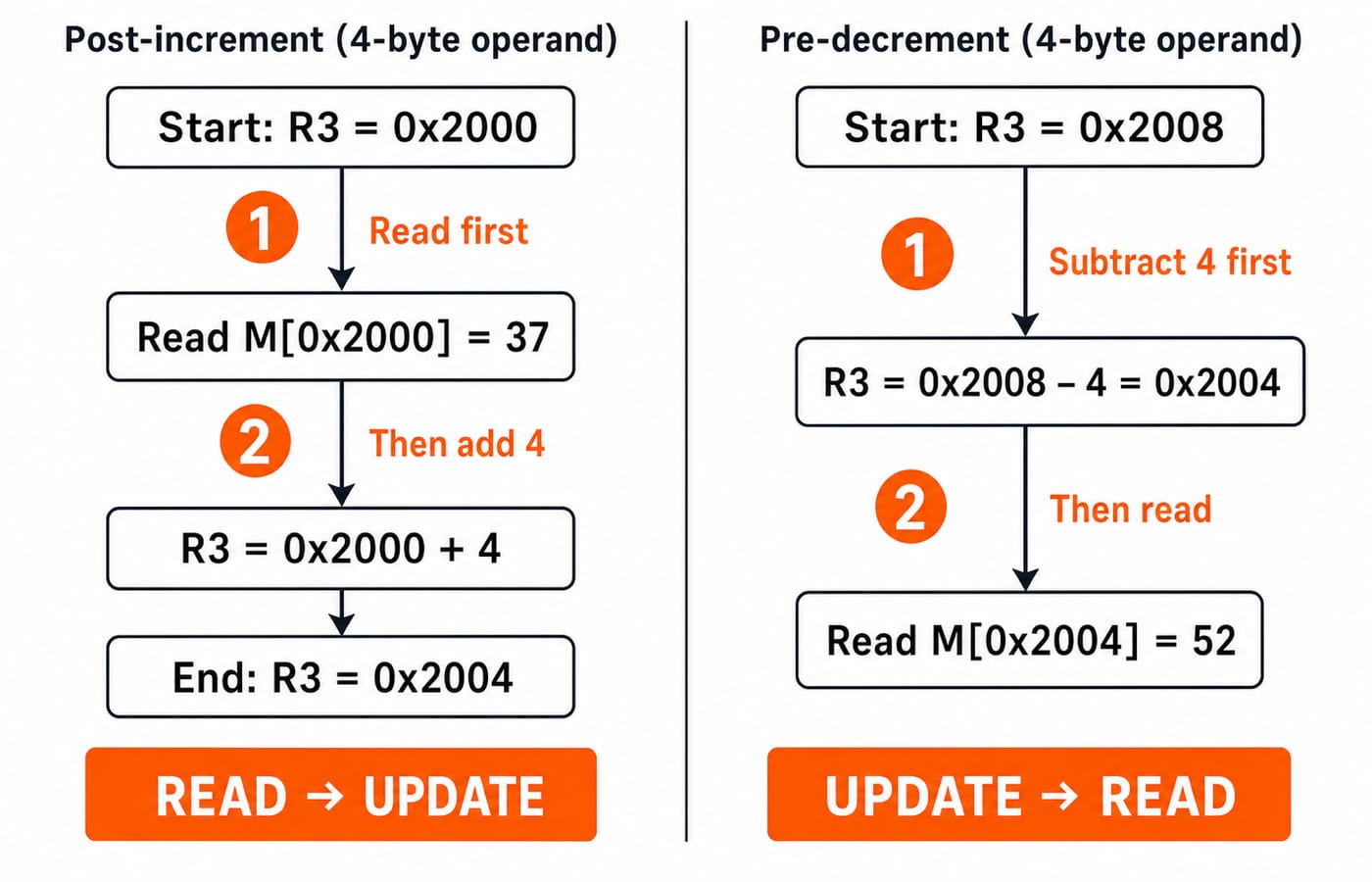
Auto-increment, auto-decrement and PC-relative order of operations
For post-increment LOAD (R3)+, use a 4-byte operand, start with R3=0x2000, and take M[0x2000]=37. First use the old register value as EA=0x2000 and read operand 37. Then update R3=0x2000+4=0x2004.
For the separate pre-decrement example LOAD -(R3), start with R3=0x2008 and M[0x2004]=52. First update R3=0x2008-4=0x2004. Then use the new value as EA=0x2004 and read operand 52.
The register changes by operand size, not automatically by one byte. For PC-relative mode, sign extension and any scaling must come from the stated architecture. With the post-fetch PC as the stated base, the calculation begins at PC_after. Compound modes can combine a base, index, displacement, and indirection; each extra addition or dereference must appear as a separate step.
The self-check is: post-increment uses the old register as EA, pre-decrement uses the new register as EA, and PC-relative adds a signed displacement to the stated PC base.
Instruction-field numericals: mode bits, address width and relative reach
Consider a separate hypothetical 32-bit instruction containing a 6-bit opcode, a 2-bit addressing-mode field, and a 4-bit register field. The remaining address or displacement field has 32-6-2-4=20 bits. The 2 mode bits can encode at most 2^2=4 distinct mode codes in this format.
If the 20-bit field is an unsigned absolute byte address, its values run from 0 through 2^20-1=1,048,575, or 0x00000 through 0xFFFFF. That covers 2^20=1,048,576 byte addresses, a 1 MiB span beginning at zero. This conclusion belongs only to the stated format.
If the same field is a signed two's-complement PC-relative displacement, a byte-scaled field reaches from -2^19 through 2^19-1, or -524,288 to +524,287 bytes. With 4-byte-word scaling, multiply both endpoints by four: -2,097,152 to +2,097,148 bytes. The positive endpoint is four bytes short of +2,097,152 because the largest signed code is one less than 2^19.
Addressing-mode traps that cost easy marks
Use each correction as a small checklist:
Wrong: report
M[EA]when only EA is asked. Why: that gives the data, not its location. Correct: stop after computing EA.Wrong: treat immediate data as an address. Why: immediate mode embeds the operand. Correct: return
Aas data.Wrong: stop after the pointer read in memory indirect mode. Why: the pointer is the EA. Correct: read
M[EA]for the operand.Wrong: add the instruction's starting address in PC-relative mode. Why: the question may specify another PC base. Correct: use the stated base,
PC_afterhere.Wrong: ignore two's-complement sign extension. Why: a negative displacement becomes a large positive value. Correct: sign-extend before addition.
Wrong: update an auto-index register in the wrong order. Why: pre and post modes form different EAs. Correct: write the read and update sequence explicitly.
Two more boundaries matter. Do not count instruction fetch when asked only for extra operand accesses unless fetch is explicitly included. Do not assume byte or word scaling when the problem does not specify it.
On scratch paper, write five lines: given values, mode formula, EA, operand, and extra reads/register update.
How exams turn addressing modes into questions
Common question patterns ask you to compute EA and operand, compare memory accesses, identify a mode from register-transfer behaviour, find remaining field bits or an addressable range, trace signed PC-relative displacement, or apply post-increment and pre-decrement in the correct order.
Use the fixed machine state for this three-part checkpoint:
Memory indirect: What are the operand and extra-read count? Answer:
0x003Cand 2, because one read obtains pointer0x1800and the next obtains the operand.Indexed: What are EA and operand? Answer:
0x0230and0x004B, because0x0200+0x0030=0x0230.Post-increment: What is
R3after the load? Answer:0x2004, because the 4-byte operand advances0x2000by four after the read.
For timed practice on EA, operand, and memory-read calculations, use the GATE Test Series.
Basic addressing modes: the short version and next step
Immediate and register modes need no data-memory EA. Direct uses the instruction field as EA. Indirect adds a pointer lookup. Register-indirect uses a register as EA. Indexed, base, and PC-relative modes add the stated components. Auto-update modes make operation order part of the answer.
Now redo the fixed-state calculations with R2=0x0040 and d=-0x0010. The indexed EA becomes 0x0200+0x0040=0x0240. The base-plus-displacement EA becomes 0x1000-0x0010=0x0FF0. The PC-relative EA becomes 0x1204-0x0010=0x11F4. The operands at these new addresses are undefined because their memory contents were not supplied.
Readers who want a guided preparation path can explore GATE Guidance by Sanchit Sir. If this is the only topic you need, first recompute every example without looking at the formulas.
Keep learning

Multiprocessor Classification: Flynn Taxonomy, Memory Models and Exam-Style Worked Examples
Learn how to choose the right multiprocessor classification axis, then solve a four-lane SIMD trace and a NUMA average-access-time problem step by step.
Updated 27 Sep 20266 min readComputer Organization & Architecture

Interrupt-Driven I/O Explained: CPU Handshake, Worked Timing Example and GATE Traps
Trace an interrupt from device request to return-from-interrupt, then compare polling, per-event interrupts, and DMA through worked timing examples.
Updated 25 Sep 20267 min readComputer Organization & Architecture
Interface Addressing Explained: Memory-Mapped vs Isolated I/O with Worked Examples
Understand what an interface address selects, how memory-mapped and isolated I/O differ, and why partial decoding creates multiple addresses for the same register.
Updated 23 Sep 20266 min readComputer Organization & Architecture
Instruction Structure in Computer Organization: Fields, Encoding and Exam Problems
Learn how opcode, register, mode and displacement fields divide an instruction word. Follow checked examples for address forms, decoding and expanding opcodes.
Updated 22 Sep 20265 min readComputer Organization & Architecture