Moore vs Mealy Machines for GATE: State Diagrams, Conversion and State Minimization, Solved
Follow one overlapping 11 detector through Mealy and Moore forms, then convert, trace and minimize finite-state machines without losing a clock.
KnowledgeGate Team
Exam prep & CS education
Updated 9 Aug 20266 min read143 views
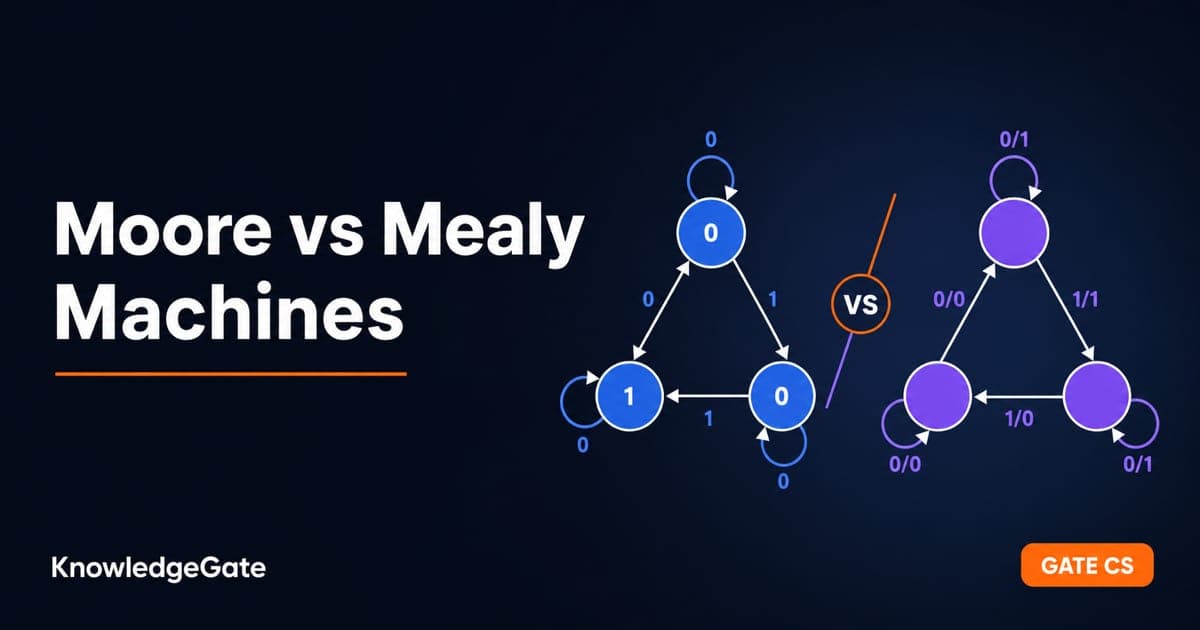
Moore and Mealy machines trip students on two things: where the output is written, and why conversion can change the number of states. Both questions reduce to where the output lives. A complete trace then settles the timing instead of leaving it to a memorised slogan.
The one rule that separates Moore and Mealy
In a Moore machine, output depends only on the present state. Write the output inside the state bubble, commonly as state/output.
In a Mealy machine, output depends on the present state and current input. Write it on the transition edge as input/output.
That difference has two practical consequences. A Mealy machine usually needs the same number or fewer states because one state can produce different outputs on different input edges. Its combinational output can also react to the current input before the next state is clocked. A Moore output changes only when the machine enters a state, so it is clock-aligned and is commonly described as appearing one clock later.
Be precise when comparing output strings. A Mealy machine produces one transition output for each input symbol. A Moore machine also has an output in its initial state before it consumes any input. State whether that initial output is included.
Worked machine: overlapping 11 detector
The target behaviour is simple: output 1 whenever the current input bit completes the pattern 11. Overlap is allowed, so input 111 contains detections at the second and third bits.
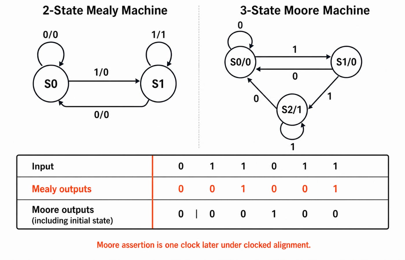
Mealy version with two states
Use these meanings:
S0: the previous bit was not 1, or no bit has arrived.S1: the previous bit was 1.
Present state | Input | Next state | Output |
|---|---|---|---|
S0 | 0 | S0 | 0 |
S0 | 1 | S1 | 0 |
S1 | 0 | S0 | 0 |
S1 | 1 | S1 | 1 |
Only the final row detects 11: the machine was already in S1, and the current input is another 1. It stays in S1, which preserves overlap for a possible next 1.
Moore version with three states
A Moore output cannot sit on the detecting edge. It needs a state whose fixed output is 1:
S0/0: no pending leading 1.S1/0: the last bit was 1.S2/1: the latest bit has just completed11.
Present state | Output | Next on 0 | Next on 1 |
|---|---|---|---|
S0 | 0 | S0 | S1 |
S1 | 0 | S0 | S2 |
S2 | 1 | S0 | S2 |
S2 goes to itself on input 1 because the latest 1 can also be the first bit of the next overlapping 11. On input 0, every state returns to S0.
Trace both machines on the same input
Use input:
0 1 1 0 1 1
The Mealy trace is:
Step | State before | Input | State after | Output |
|---|---|---|---|---|
1 | S0 | 0 | S0 | 0 |
2 | S0 | 1 | S1 | 0 |
3 | S1 | 1 | S1 | 1 |
4 | S1 | 0 | S0 | 0 |
5 | S0 | 1 | S1 | 0 |
6 | S1 | 1 | S1 | 1 |
Its transition-output string is 0 0 1 0 0 1.
The Moore state path is:
S0 → S0 → S1 → S2 → S0 → S1 → S2
The first S0 is the initial state. Including its initial output, the Moore state-output string is:
0 | 0 0 1 0 0 1
If outputs are sampled after each state transition, the six outputs paired with the six consumed symbols are again 0 0 1 0 0 1. In a clocked circuit, the Mealy output can assert from the input and current state during the cycle, while the Moore detection asserts after the active edge places the machine in S2. That is the one-clock timing distinction. The apparent contradiction disappears once the sampling convention and initial Moore output are stated.
Converting Mealy to Moore and back
For Mealy to Moore, inspect the outputs on edges entering each Mealy state. If one state is entered with different output values, split it into one Moore copy for each incoming output value.
In the detector, Mealy state S1 is entered from S0 on 1/0 and from itself on 1/1. A Moore state cannot have both output 0 and output 1, so S1 splits into S1/0 and S2/1. That is why two Mealy states become three Moore states. Redirect every transition to the copy carrying that transition's output.
An initial-state output may require a separate choice or dummy state because a Mealy machine has no output before the first transition. State the convention the question uses.
For Moore to Mealy, remove the output from each state and place that value on every edge entering it. The conversion itself keeps the state count, and later equivalent-state removal can reduce it. It never needs more states. In this example, the Mealy forms corresponding to Moore states S1 and S2 have identical future transition and output behaviour, so they merge into the two-state detector.
The safe headline is: Moore-to-Mealy does not increase states; Mealy-to-Moore may increase them.
State minimization by partition refinement
Minimize a Moore machine mechanically:
Remove unreachable states.
Form
P0by grouping states with the same output.For each state, record which current partition its transition reaches on each input.
Split a group when two members have different signatures.
Repeat until no group splits. Each final group becomes one state.
Take a Moore machine with states A, B and C carrying outputs 0, 0 and 1, starting in A:
State | Output | Next on 0 | Next on 1 |
|---|---|---|---|
A | 0 | B | C |
B | 0 | A | C |
C | 1 | C | C |
The first partition is:
P0 = {{A,B}, {C}}
Call the two groups G0={A,B} and G1={C}. State A goes to (G0,G1) on inputs (0,1): its 0-transition reaches B in G0, and its 1-transition reaches C in G1. State B gives the same pair, reaching A in G0 and C in G1.
Their outputs match and their transition signatures match, so A and B remain together. C has output 1 and stays separate. The partition is stable, giving two equivalence classes: {A,B} and {C}. The minimized quotient machine has 2 states.
This is the same refinement logic used in DFA minimization. For a Mealy machine, begin by grouping states with identical output behaviour for each input, then refine by destination groups.
Traps that cost the marks
Moore output belongs inside a state; Mealy output belongs on an edge.
Do not assume conversion preserves the state count.
Include or exclude the initial Moore output explicitly when tracing a sequence.
Preserve overlaps in a detector. After detecting
11, another 1 must allow another detection.Remove unreachable states before partition refinement.
Merge states only when both immediate outputs and future partition destinations match.
How GATE tests finite-state machines
Questions commonly ask for the minimum states required for a behaviour, the state count after conversion, or the output sequence for a given input. The fastest check is a transition table. It exposes missing inputs, incorrect overlap handling and output-placement errors more clearly than a crowded diagram.
FSM coverage across Digital Electronics and Theory of Computation, along with any marks assigned to it, is cycle-specific. Confirm the current syllabus in the brochure on the official GATE portal of the organising IIT.
The short version and next step
Output in the state means Moore. Output on the edge means Mealy. Moore-to-Mealy does not add states, Mealy-to-Moore can, and partition refinement merges states only when their outputs and destination signatures agree.
Connect the machines to their hardware through sequential circuits, flip-flops and counters, then practise the shared refinement method with DFA minimization for GATE. The complete subject path is in GATE Guidance by Sanchit Sir, with the wider map on the GATE category. KnowledgeGate's question bank has about 1,500 Digital Electronics questions covering the sequential-circuit and FSM material used here.
Keep learning

ISRO Scientist/Engineer CS Syllabus vs GATE CS: The Subject Overlap Map
See which core CS subjects transfer directly from GATE to ISRO, what drops out, how the question texture changes and where an ISRO-specific polish helps.
Updated 5 Oct 20264 min readGATE Strategy & Roadmap

Union-Find for GATE: Union by Rank, Path Compression and the Near-Constant Bound
Trace seven unions, inspect the final ranks, then compress the deepest path by hand. The worked forest makes the inverse-Ackermann bound much less mysterious.
Updated 1 Oct 20265 min readGATE Strategy & Roadmap

RAID Levels for GATE: Striping, Mirroring, Parity and the Two Capacity Formulas
Stop memorising RAID names in isolation. Tie each level to usable capacity, failure tolerance and write cost, then test the formulas on one eight-disk array.
Updated 26 Sep 20265 min read58 viewsGATE Strategy & Roadmap

Memory Interfacing for GATE: Chip-Count and Address-Decoding Numericals, Fully Worked
Separate words from bits, split the address correctly, and verify the result with a gap-free hexadecimal map. This guide works through depth and width expansion step by step.
Updated 24 Sep 20265 min read55 viewsGATE Strategy & Roadmap