3D Object Representation, Geometric Transformations and Viewing: A Worked Pipeline
Track three vertices through a complete 3D graphics pipeline. The worked example makes matrix order, camera depth and viewport conversion explicit.
KnowledgeGate Team
Exam prep & CS education
Updated 22 Aug 20266 min read
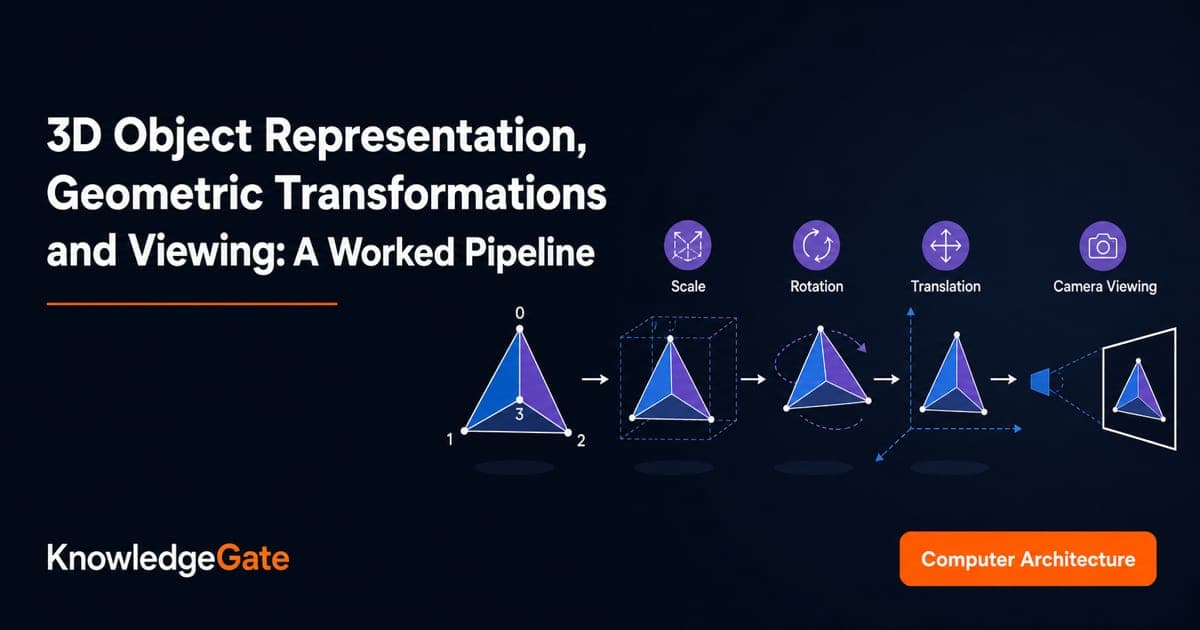
Students often learn polygon meshes, transformation matrices and viewing as separate definitions. The trouble begins when a problem connects them: it becomes easy to lose track of whether a coordinate belongs to the object, the world, the camera or the final screen. One wrong matrix order, or a missed perspective divide, changes every value that follows.
The object is a triangular mesh face with vertices v0, v1 and v2. Its coordinates pass through scaling, z-axis rotation, translation, camera transformation, perspective projection and mapping to an 800 x 600 viewport.
Represent a 3D object before trying to move it
Different representations preserve different facts.
Representation | What it preserves | One limitation |
|---|---|---|
Wireframe | Vertices and edges | It does not identify surfaces |
Polygon mesh or boundary representation | Vertices and ordered faces | Curves need polygon approximation |
Constructive solid geometry | Primitives and Boolean operations | Display conversion can be costly |
Parametric or implicit surface | Shape equations or parameters | Editing or rasterisation may need conversion |
No form is always best. We use an indexed polygon mesh because it keeps topology explicit while transformations act on vertices.
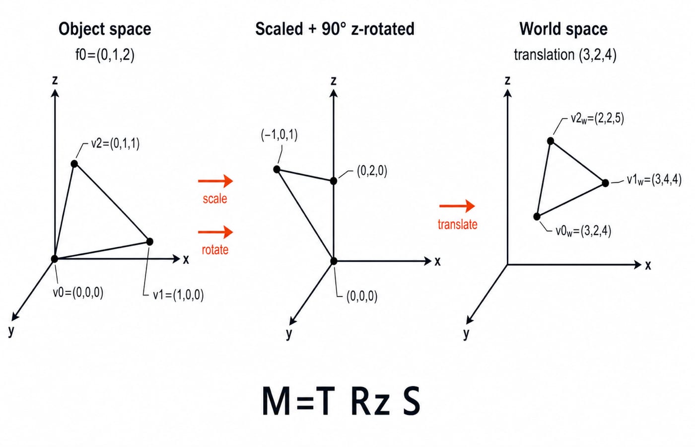
In object coordinates, define v0 = (0, 0, 0), v1 = (1, 0, 0) and v2 = (0, 1, 1). The face is f0 = (0, 1, 2), with edges (0,1), (1,2) and (2,0). It stores indices rather than coordinate copies, while the order sets a consistent winding convention.
From v0, e1 = v1 - v0 = (1, 0, 0) and e2 = v2 - v0 = (0, 1, 1). Their cross product is e1 x e2 = (0, -1, 1). It can support orientation or later visibility tests, without introducing lighting.
Keep the coordinate spaces and matrix convention explicit
The pipeline is:
object coordinates -> world coordinates -> camera/view coordinates -> projected image coordinates -> viewport pixels
The model transform places geometry in the world. The view transform expresses it relative to the camera. Projection produces image coordinates, and viewport mapping converts the image window into pixels. Never compare coordinates from different stages as if they share one frame.
We use 4 x 1 column vectors, homogeneous point [x, y, z, 1]^T, and matrices acting on the left. Read composites from right to left. Translation fits 4 x 4 multiplication because a point ends in 1; a direction ends in 0, so translation does not move it.
Review the matrix operations behind this pipeline and place those operations in the wider mathematics map. Use them to refresh matrix multiplication and related mathematical prerequisites.
Worked example, part one: object space to world space
Apply scale (2, 1, 1), then a 90 degrees counterclockwise rotation about positive z, then translation (3, 2, 4):
S = [[2,  0, 0, 0],
     [0,  1, 0, 0],
     [0,  0, 1, 0],
     [0,  0, 0, 1]]

Rz = [[0, -1, 0, 0],
      [1,  0, 0, 0],
      [0,  0, 1, 0],
      [0,  0, 0, 1]]

T = [[1, 0, 0, 3],
     [0, 1, 0, 2],
     [0, 0, 1, 4],
     [0, 0, 0, 1]]
With column vectors, the composite is M = T Rz S, not S Rz T. Multiplication gives:
M = [[0, -1, 0, 3],
     [2,  0, 0, 2],
     [0,  0, 1, 4],
     [0,  0, 0, 1]]
For a full check on v1:
M[1, 0, 0, 1]^T = [0(1) - 1(0) + 3, 2(1) + 0(0) + 2, 1(0) + 4, 1]^T = [3, 4, 4, 1]^T.
Vertex | Object coordinates | World coordinates |
|---|---|---|
|
|
|
|
|
|
|
|
|
The staged check for v2 agrees: scaling gives (0,1,1), rotation gives (-1,0,1), and translation gives (2,2,5).
Worked example, part two: camera coordinates and perspective projection
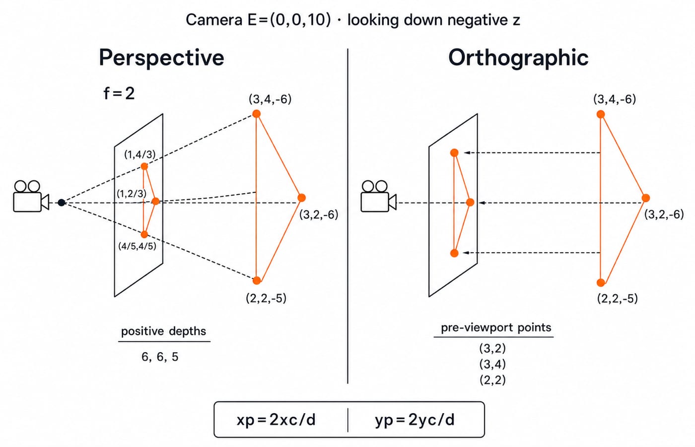
Put the camera at E = (0,0,10), aligned with the world axes and looking along negative z. There is no camera rotation, so the view step subtracts the eye position:
Vertex | Camera coordinates | Positive depth |
|---|---|---|
|
|
|
|
|
|
|
|
|
For focal length f = 2, use xp = f xc / d and yp = f yc / d:
v0p = (2 x 3/6, 2 x 2/6) = (1, 2/3), approximately(1, 0.667).v1p = (2 x 3/6, 2 x 4/6) = (1, 4/3), approximately(1, 1.333).v2p = (2 x 2/5, 2 x 2/5) = (4/5, 4/5), or(0.8, 0.8).
Only now compare orthographic projection. Dropping camera-space depth retains (xc,yc), so the pre-viewport points would be (3,2), (3,4) and (2,2). A view transform changes the coordinate frame. A projection changes how depth affects the image. They are not synonyms.
Finish the pipeline with clipping, viewport mapping and depth
Take projected window 0 <= x <= 2, 0 <= y <= 2 and an 800 x 600 viewport with a bottom-left origin. The mapping is X = (xp/2) x 800 and Y = (yp/2) x 600.
v0:X = (1/2) x 800 = 400,Y = ((2/3)/2) x 600 = 200, so the pixel is(400,200).v1:X = (1/2) x 800 = 400,Y = ((4/3)/2) x 600 = 400, so the pixel is(400,400).v2:X = ((4/5)/2) x 800 = 320,Y = ((4/5)/2) x 600 = 240, so the pixel is(320,240).
All points are inside the window, so no clipping is needed. A top-left origin would require a y flip, but our chosen answers use bottom left.
A real pipeline clips primitives against the viewing volume, performs the perspective divide, maps survivors to pixels and uses a depth buffer during rasterisation. Under our positive-depth convention, the smaller visible depth is nearer. The rasteriser compares interpolated fragment depths, not only vertex depths.
Traps and the ways an exam can join the concepts
Trap | What goes wrong | Correct check | Evidence from the example |
|---|---|---|---|
Use | Translation is transformed | Read column operations right to left |
|
Mix object and world coordinates | Frames are confused | Label each coordinate space |
|
Insert row-vector rules | Order becomes inconsistent | Declare the convention first | Points are |
Equate view and projection | Frame and depth effects blur | Finish view before projection |
|
Drop z without dividing | Perspective disappears | Divide by positive depth |
|
Map before clipping | Rejected geometry reaches pixels | Clip first | Points are tested against |
Flip y silently | The origin is wrong | Declare the screen origin |
|
Combined questions may ask you to recover a vertex, choose the composite, distinguish point from direction, calculate camera depth, compare projections, map a point, or identify clipping. Check them by substituting one vertex, reading right to left, inspecting the fourth coordinate, calculating -zc, applying both projection rules, using the viewport equations, and locating the stage before pixel mapping.
Test the joins between ideas by transforming one fresh vertex, projecting it under both rules, and checking whether its mapped point lies inside the window.
3D representation and viewing: the short version and next step
Store geometry with explicit topology, declare the coordinate convention, compose model transforms in the correct order, move world points into camera space, apply the depth rule, then clip and map the result to the viewport. Without looking back, recover M = [[0,-1,0,3], [2,0,0,2], [0,0,1,4], [0,0,0,1]], world vertices (3,2,4), (3,4,4), (2,2,5), projected points (1,2/3), (1,4/3), (4/5,4/5), and pixels (400,200), (400,400), (320,240).
For a structured route through connected Computer Science topics, continue with ZERO TO HERO (Complete Course). Use the CS Fundamentals catalog to place this graphics pipeline within the wider subject map.
Keep learning
Graphical Method in Linear Programming: Feasible Region, Corner Points and Optimality with a Worked Example
Learn the two-variable graphical method in the right order, then solve and audit a complete maximisation model without trusting the sketch alone.
Updated 21 Oct 20265 min readEngineering Mathematics

Duality in LP: Construct the Dual, Solve a Worked Example, and Apply Key Properties
Learn a reliable matrix-first method to form an LP dual, solve both programs to value 21, and use duality properties to check optimality and avoid sign errors.
Updated 17 Oct 20266 min readEngineering Mathematics

Commutative Property and Abelian Groups: Tests, Worked Examples and Exam Traps
Learn how to separate commutativity from the other group axioms, test custom operations step by step, and avoid the usual classification traps.
Updated 13 Oct 20266 min readEngineering Mathematics

Closure, Semigroup and Monoid: Worked Algebraic Structure Examples
Learn a reliable order for testing closure, associativity and identity. Worked tables and counterexamples show exactly when a structure becomes a semigroup or monoid.
Updated 9 Oct 20266 min readEngineering Mathematics