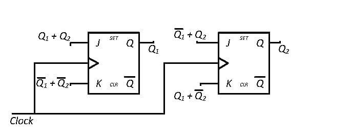
A 2-bit synchronous counter using two J-K flip flops is shown. The expressions…
GATE · 2018 · IN · Instrumentation Engineering
A 2-bit synchronous counter using two J-K flip flops is shown. The expressions for the inputs to the J-K flip flops are also shown in the figure. The output sequence of the counter starting from Q₁Q₂ = 00 is
- A.
00 → 11 → 10 → 01 → 00 ···
- B.
00 → 01 → 10 → 11 → 00 ···
- C.
00 → 01 → 11 → 10 → 00 ···
- D.
00 → 10 → 11 → 01 → 00 ···
Attempted by 10 students.
Sign up free to check your answer
Sign up freeLoading lesson…