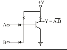
The following diagram depicts ____ logic.
2013
The following diagram depicts ____ logic.
Answer: C. Diode-transistor — Concept: In digital electronics, a logic family is classified by identifying which component performs the logic-gating function and which component performs…
- A.
Diode
- B.
Transistor
- C.
Diode-transistor
- D.
Resistor
Attempted by 308 students.
Show answer & explanation
Correct answer: C
Concept: In digital electronics, a logic family is classified by identifying which component performs the logic-gating function and which component performs the amplifying/switching function. Diode-Transistor Logic (DTL) is the family in which a diode network gates the inputs and a transistor amplifies/switches the output — this split is the defining rule for naming a logic family from its circuit diagram.
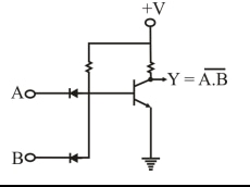
Application: In the given circuit, inputs A and B each pass through an input diode into a common node that is tied through a pull-up resistor to +V and connected to the base of an NPN transistor; the transistor's collector is pulled up to +V through another resistor and gives the output Y, with its emitter grounded. The diode pair performs the input logic-gating, while the transistor performs the amplifying/switching that produces Y = NOT(A AND B).
Diode alone would mean only the passive input-gating diodes are present, with no active amplifying/switching stage — but the diagram clearly shows an active transistor driving the output.
Transistor alone would mean the circuit switches directly on the raw inputs with no separate diode network gating them first — but the diagram shows two input diodes feeding the transistor's base.
Resistor alone would describe only the passive pull-up/bias elements at the collector and diode nodes, which set current levels but perform no logic-gating or switching function themselves.
Diode-transistor accounts for every active/gating element in the diagram together: the input diode network for gating and the transistor stage for switching.
Result: Because the circuit combines an input diode-gating network with a transistor amplifying/switching stage, the diagram depicts Diode-Transistor Logic (DTL).