Refer to the monostable multivibrator circuit in the figure below. The trigger…
2013
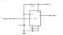
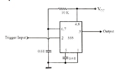
Refer to the monostable multivibrator circuit in the figure below. The trigger terminal (pin 2 of the IC ) is driven by a symmetrical pulsed waveform of 10 kHz. Determine the duty cycle of the output waveform.
Answer: B. 0.55 — Solution: Step 1 – Output pulse width (Ton): For a monostable 555, Ton = 1.1 · R · C. R = 10 kΩ = 10 × 10³ Ω C = 0.01 μF = 0.01 × 10⁻⁶ F = 1.0 × 10⁻⁸ F Ton =…
- A.
0.56
- B.
0.55
- C.
0.57
- D.
0.58
Attempted by 223 students.
Show answer & explanation
Correct answer: B
Solution:
Step 1 – Output pulse width (Ton): For a monostable 555, Ton = 1.1 · R · C.
R = 10 kΩ = 10 × 10³ Ω
C = 0.01 μF = 0.01 × 10⁻⁶ F = 1.0 × 10⁻⁸ F
Ton = 1.1 · R · C = 1.1 · 10 × 10³ · 1.0 × 10⁻⁸ = 110 × 10⁻⁶ s = 110 μs
Step 2 – Input trigger characteristics and effect on triggering:
Input frequency = 10 kHz → input period = 1/10 kHz = 100 μs.
Because Ton (110 μs) is longer than the input period (100 μs), the monostable will not respond to every input edge. Only alternate edges (every 200 μs) will produce output pulses.
Step 3 – Output period, frequency and duty cycle:
Output repetition period = 2 × input period = 2 × 100 μs = 200 μs (output frequency = 5 kHz).
Duty cycle = Ton / Tout = 110 μs / 200 μs = 0.55
Final answer: Duty cycle = 0.55