Data Link Layer Framing Explained: Byte Stuffing, Bit Stuffing and a Cross-Concept Numerical
Frame one four-byte payload in two ways, decode it, and then reuse the verified frame sizes in link-load and Stop-and-Wait calculations.
KnowledgeGate Team
Exam prep & CS education
Updated 1 Oct 20266 min read
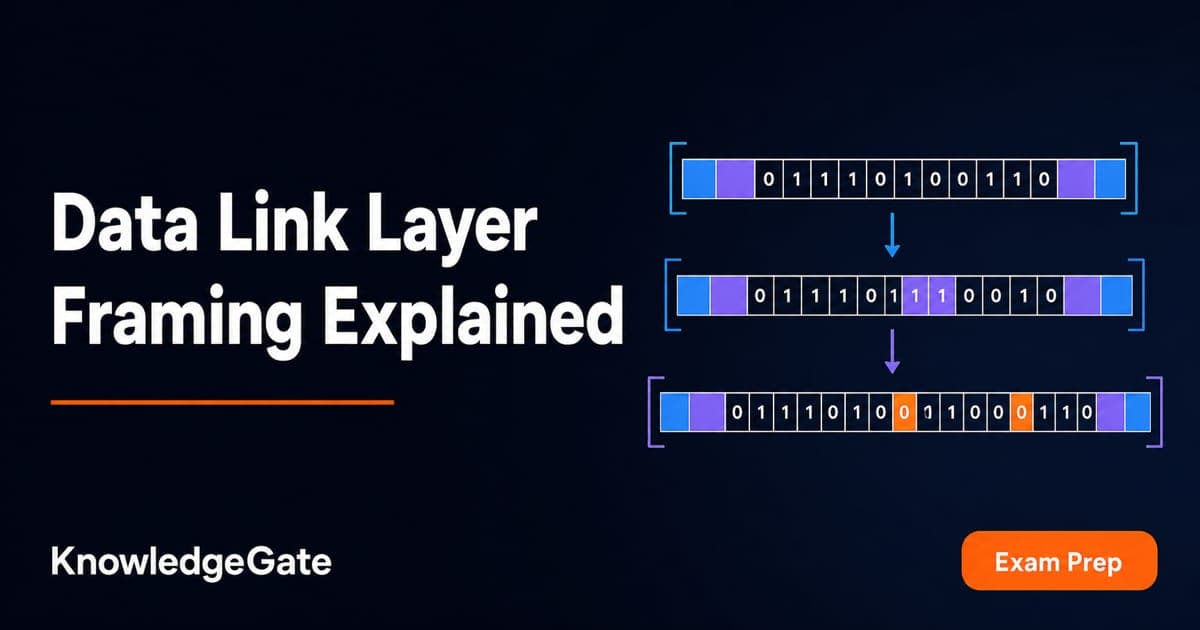
A four-byte payload containing reserved byte values and repeated runs of 1s exposes the difference between byte-oriented and bit-oriented framing. Keeping payload size, transmitted frame size, offered link load and Stop-and-Wait cycle separate prevents one overhead count from contaminating the next calculation.
For payload 0x41 0x7E 0x7D 0xF8, the stated byte-oriented convention transmits 64 bits while the bit-oriented convention transmits 51. At 10,000 frames/s, those complete frame sizes produce offered loads of 640 kb/s and 510 kb/s before they enter separate Stop-and-Wait cycles on the same 1 Mb/s link.
1. Why the data link layer needs framing
A link carries a continuous transmission. Framing divides it into units whose boundaries a receiver can recognise. Stuffing stops payload data imitating a delimiter. Error detection checks for changed bits, while flow control decides when another frame may be sent. These roles are separate.
Approaches include a length or character-count field, byte-oriented sentinels with an escape byte, bit-oriented sentinels with zero insertion after five consecutive 1 bits, and coding violations using spare physical-layer symbols. The three methods differ in how they identify frame boundaries. Protocols need not share one flag or rule.
The earlier DLL Framing in Computer Networks: Methods, Bit Stuffing and Worked Examples provides the four-method taxonomy and separate examples. Holding one payload constant across byte and bit stuffing instead produces two frame sizes that feed the link-load and Stop-and-Wait calculations. For the broader subject map, follow CS Fundamentals for Exams & Placements.
2. Fix the payload and conventions before doing any arithmetic
The payload is:
0x41 0x7E 0x7D 0xF8
Its 32-bit form is 01000001 01111110 01111101 11111000. For byte stuffing, let FLAG = 0x7E and ESC = 0x7D. Replace a payload 0x7E or 0x7D with ESC, followed by the original byte XOR 0x20. For bit stuffing, use boundary flag 01111110 and insert a 0 after every run of five consecutive payload 1 bits.
The simplified formats are FLAG | stuffed payload bytes | FLAG and 01111110 | stuffed payload bits | 01111110. Both exclude address, control, FCS, preamble and inter-frame gap.
A length field has another synchronisation risk. If a one-byte count includes itself, frames could be 05 41 7E 7D F8 and 03 10 20. If 05 becomes 08, the receiver consumes 41 7E 7D F8 03 10 20 as one body, swallowing the next frame. This illustrates count corruption, not an unusable method.
3. Worked byte-stuffing frame
Scan the payload only, never the boundary flags. Keep 0x41 and 0xF8 unchanged.
0x7E XOR 0x20 = 0x5E, so payload7Ebecomes7D 5E.0x7D XOR 0x20 = 0x5D, so payload7Dbecomes7D 5D.
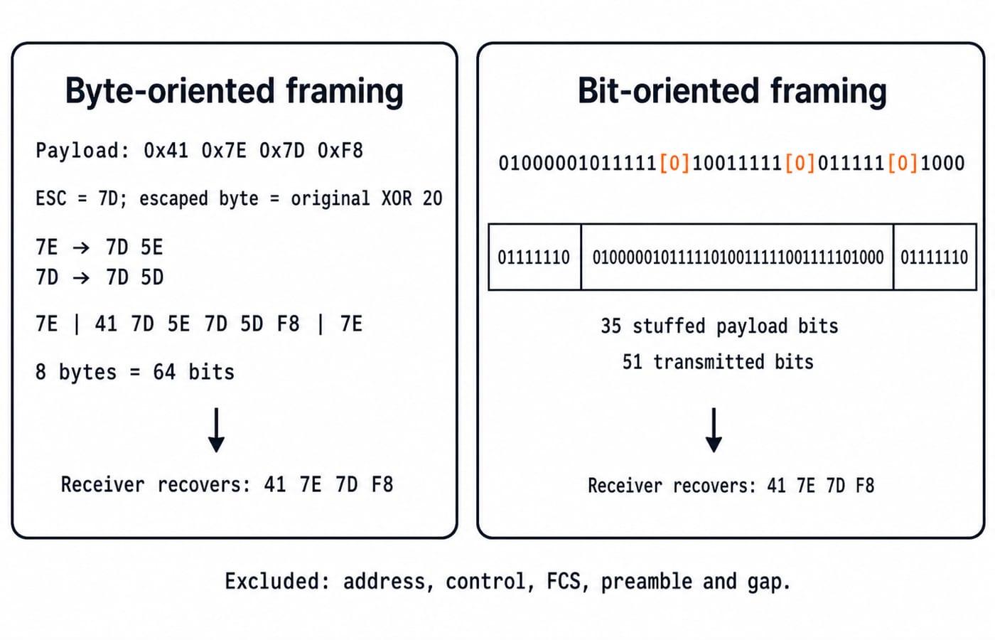
The stuffed payload is 41 7D 5E 7D 5D F8. Adding the boundaries gives 7E | 41 7D 5E 7D 5D F8 | 7E.
That is 8 bytes, or 64 bits: 32 payload bits, 16 bits from two inserted escape bytes, and 16 bits from two flags. Payload efficiency is 32/64 = 50%. The frame adds 32 transmitted bits relative to the original payload.
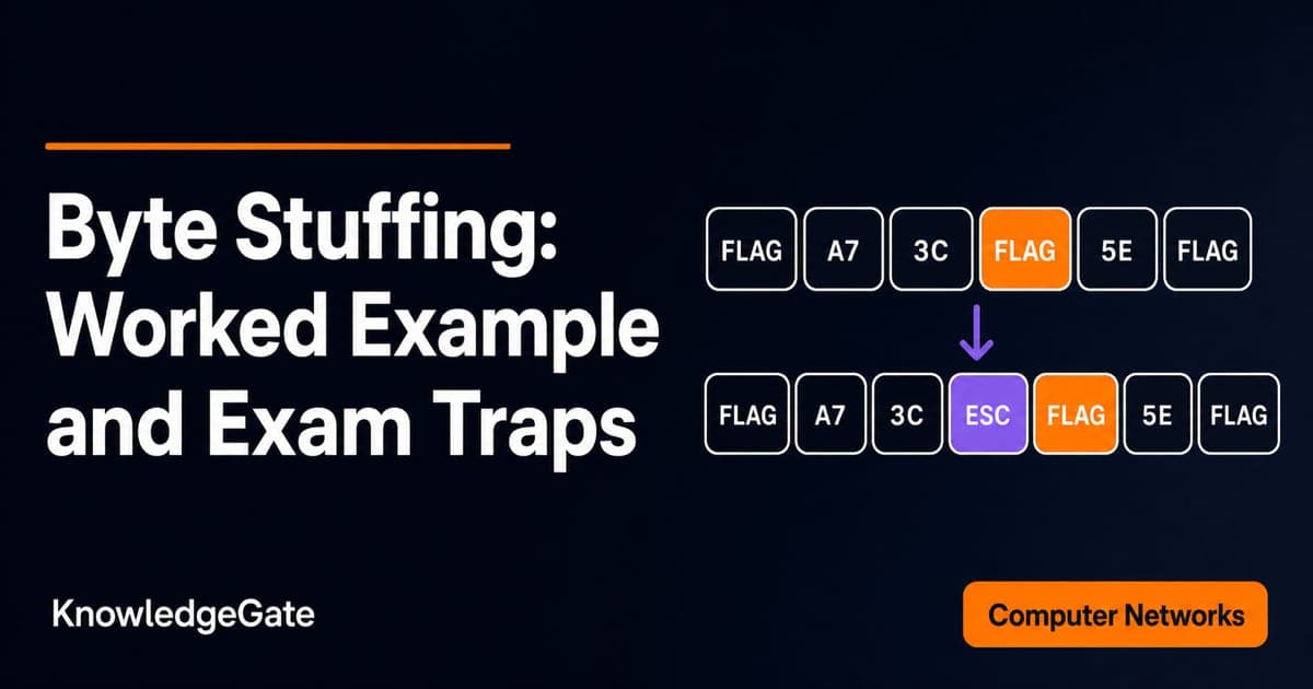
The receiver discards the flags and XORs each byte after ESC with 0x20, recovering 41 7E 7D F8. The outer 7E values are delimiters. The recovered inner 7E is data because it arrived through an escape sequence. For a decoder-state treatment of prefix escaping, including incomplete escape sequences and a byte-only transmission-time numerical, use Byte Stuffing in Computer Networks: Worked Framing Example and Exam Traps. Here the XOR convention keeps the same four-byte payload available for the cross-method comparison.
4. Worked bit-stuffing frame
Concatenate the bytes before scanning: 01000001011111100111110111111000. Continue the five-ones count across displayed byte boundaries.
The marked result is 01000001011111[0]10011111[0]011111[0]1000. Exactly three zeroes are inserted, giving 01000001011111010011111001111101000, a 35-bit stuffed payload.
With two 8-bit flags, the transmitted length is 8 + 35 + 8 = 51 bits. The 19 bits beyond the payload are three stuffed zeroes plus 16 boundary bits. Payload efficiency is 32/51 = 62.75% approximately, and overhead is 19/51 = 37.25% of the transmitted frame.
Inside the boundaries, the receiver removes a 0 following five received 1 bits. It recovers 32 bits and regroups them as 41 7E 7D F8. Byte stuffing responds to byte values, while bit stuffing responds to bit runs. Counting 0x7E bytes cannot predict bit overhead. For sender pseudocode, boundary cases and a longer 21-bit trace, use Bit Stuffing Algorithm: Worked Encoding, De-stuffing and Exam Traps. Keeping the same four-byte payload makes the 64-bit and 51-bit complete frames directly comparable.
5. Frame overhead becomes offered link load
Continuous offered load is separate from Stop-and-Wait. At 10,000 frames/s on a 1 Mb/s link, the original payload rate is 10,000 x 32 = 320,000 bit/s = 320 kb/s.
Format | Complete frame | Offered load | Link capacity used |
|---|---|---|---|
Byte stuffed | 64 bits |
| 64% |
Bit stuffed | 51 bits |
| 51% |
This is not a universal ranking. Here, byte stuffing adds two escape bytes, while bit stuffing adds three bits. Another payload or convention can change the gap.
An 80% load ceiling supplies 800,000 bit/s. The maximum whole-frame rates are floor(800,000/64) = 12,500 frames/s and floor(800,000/51) = 15,686 frames/s. Check the second result: 15,686 x 51 = 799,986 bit/s, but 15,687 x 51 = 800,037 bit/s, which exceeds the ceiling.
6. Carry the frame sizes into Stop-and-Wait
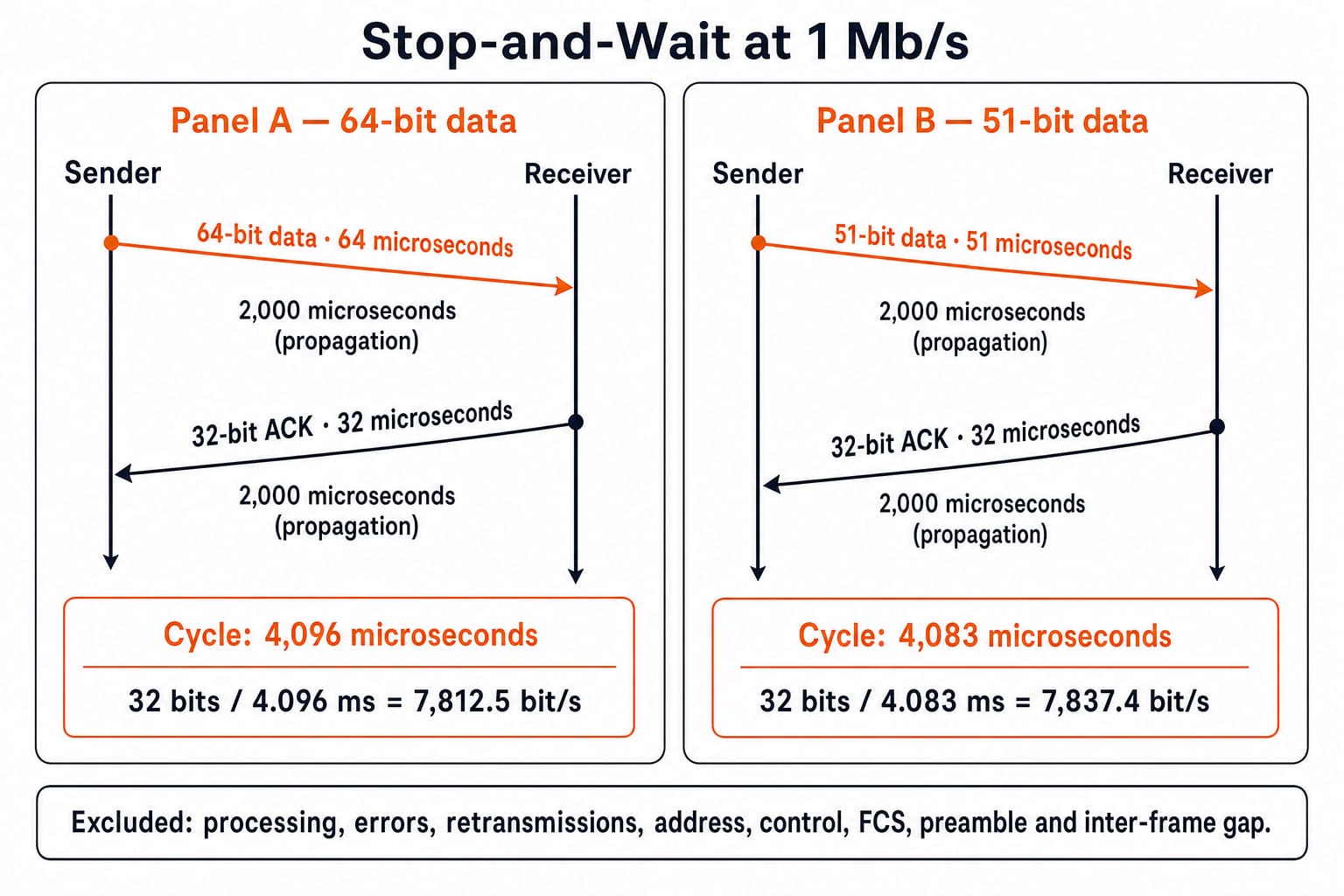
The Stop-and-Wait scenario has one outstanding data frame, a 1 Mb/s link rate, 2 ms one-way propagation, a complete 32-bit ACK, zero processing delay and no errors. At 1 Mb/s, each transmitted bit takes 1 microsecond.
Byte-oriented cycle:
64 + 2,000 + 32 + 2,000 = 4,096 microseconds = 4.096 ms. Useful throughput is32/0.004096 = 7,812.5 bit/s.Bit-oriented cycle:
51 + 2,000 + 32 + 2,000 = 4,083 microseconds = 4.083 ms. Useful throughput is32/0.004083 = 7,837.4 bit/sapproximately.
Bit stuffing saves 13 bits here, but propagation dominates, so throughput changes only slightly. Do not combine this single-frame cycle with the earlier offered-load scenario. For connected revision, use Computer Science Fundamentals for Placements by Sanchit Sir.
7. How mixed-concept framing solutions go wrong
Questions may ask you to identify a method, encode or decode, count inserted symbols, calculate efficiency or load, or carry the final size into a delay formula. A mixed stem chains two or three of those steps, as in the offered-load and Stop-and-Wait calculations using the same two frames.
Watch these traps:
Do not stuff boundary flags or reset the ones count at a printed byte boundary.
Do not treat
[0]notation as transmitted brackets.Do not confuse payload length with complete frame length or add fields that the format excludes.
For Stop-and-Wait throughput, divide useful bits by the full delivery cycle when that is what the question asks.
Compare like units only.
8. Data link layer framing in the short version
The calculation is reliable when three invariants hold: de-stuffing recovers exactly 32 payload bits, transmitted length equals the payload plus only the stated stuffing and flags, and every downstream formula uses the complete 64-bit or 51-bit frame rather than the original 32-bit payload. Both methods preserve the data; only their data-dependent overhead differs.
For a self-check, change the payload to 0x41 0x42 0x43 0x44. No byte needs escaping, so the byte-oriented frame is 6 bytes or 48 bits. The payload also contains no run of five 1 bits, so the bit-oriented frame is 32 + 16 = 48 bits. At 10,000 frames/s, either needs 10,000 x 48 = 480 kb/s. The earlier 64-versus-51 result came from data-dependent stuffing, not the method names alone.
Keep learning
Computer Networks Hardware Basics: Devices, Domains and Worked Examples
Learn what hubs, switches, routers, gateways and access points actually do, then count network domains and trace frames through a two-LAN topology.
Updated 6 Oct 20266 min readComputer Networks
Byte Stuffing in Computer Networks: Worked Framing Example and Exam Traps
Learn a precise byte-stuffing convention, trace a payload containing both FLAG and ESC, reverse it safely, and calculate frame overhead and transmission time.
Updated 26 Sep 20266 min readComputer Networks
Go-Back-N Protocol Explained: Sliding Windows, Worked Numericals and Exam Traps
Trace Go-Back-N through a lost frame, calculate its legal window and link utilisation, and avoid the ACK and wrap-around traps that spoil numericals.
Updated 24 Sep 20266 min readComputer Networks

Network Protection Explained: Firewalls, Segmentation and a Worked ACL Example
Learn a reusable trust-boundary model for network protection, then trace allowed and blocked traffic through a five-zone web service and its ordered firewall rules.
Updated 23 Sep 20265 min readComputer Networks