What is the output of the following logic diagram? In the given options, ⊕…
2018
What is the output of the following logic diagram? In the given options, ⊕ represents XOR operation, whereas ⊗ represents XNOR operation.
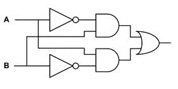
Answer: A. A⊕B — The logic circuit has two parallel paths feeding into a final OR gate. The top path inverts A to get not-A, which is ANDed with B to produce not-A times B.…
- A.
A⊕B
- B.
A⊗B
- C.
AB
- D.
A'B'
Attempted by 462 students.
Show answer & explanation
Correct answer: A
The logic circuit has two parallel paths feeding into a final OR gate. The top path inverts A to get not-A, which is ANDed with B to produce not-A times B. The bottom path inverts B to get not-B, which is ANDed with A to produce A times not-B. The OR gate combines these outputs into not-A times B plus A times not-B, which corresponds to the XOR operation.
Loading lesson…