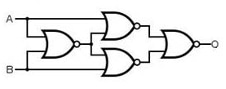
The following logic diagram is equivalent to ______ gate.
2018
The following logic diagram is equivalent to ______ gate.
Answer: D. XNOR — ConceptA NOR gate outputs 1 only when all its inputs are 0, i.e. its output is the complement of the OR of its inputs: (X + Y)'. NOR is a universal gate, so…
- A.
XOR
- B.
NAND
- C.
NOR
- D.
XNOR
Attempted by 677 students.
Show answer & explanation
Correct answer: D
Concept
A NOR gate outputs 1 only when all its inputs are 0, i.e. its output is the complement of the OR of its inputs: (X + Y)'. NOR is a universal gate, so any logic function can be built from NOR gates alone. Two algebraic tools reduce such a network: De Morgan's law, which rewrites a complemented sum as a product of complements, (X + Y)' = X'·Y'; and the complement law together with distribution, X'·(X + Y) = X'X + X'Y = X'Y, since X'X = 0. The standard equivalence (XNOR) function is the one whose output is 1 exactly when the two inputs are the same; its Boolean expression is AB + A'B'.
Applying it to this circuit
Label the inputs A (top) and B (bottom) and trace the four NOR gates left to right. Note that the small open circle at the very end of the output line is just the output terminal/node marker, not an extra inverting bubble: there is exactly one inverting bubble on the final gate.
First (left) NOR: inputs A and B give G1 = (A + B)'.
Top-middle NOR: inputs A and G1 give G2 = (A + G1)'.
Bottom-middle NOR: inputs G1 and B give G3 = (G1 + B)'.
Final (right) NOR: inputs G2 and G3 give the output O = (G2 + G3)'.
Now reduce each intermediate output with those two identities, one gate at a time:
Top-middle gate: G2 = (A + G1)' = A'·G1' by De Morgan's law.
Since G1' = ((A + B)')' = A + B, this gives G2 = A'(A + B) = A'A + A'B = A'B, because A'A = 0.
Bottom-middle gate: G3 = (G1 + B)' = G1'·B' = (A + B)B' = AB' + BB' = AB', because BB' = 0.
Final gate: O = (G2 + G3)' = (A'B + AB')'.
A'B + AB' is the non-equivalence (difference) function, so its complement is the equivalence function: O = (A'B)'·(AB')' = (A + B')(A' + B) = AA' + AB + A'B' + BB' = AB + A'B'.
So the network's output is O = AB + A'B' — it is 1 exactly when A and B carry the same value.
Cross-check by truth table
Evaluating all four input combinations confirms the output is 1 only when A and B are equal:
A | B | G1 | G2 | G3 | Output O |
|---|---|---|---|---|---|
0 | 0 | 1 | 0 | 0 | 1 |
0 | 1 | 0 | 1 | 0 | 0 |
1 | 0 | 0 | 0 | 1 | 0 |
1 | 1 | 0 | 0 | 0 | 1 |
The output column is 1 for A=B (00 and 11) and 0 when the inputs differ (01 and 10). That is precisely the equivalence function AB + A'B', so the circuit is equivalent to an XNOR gate.