What are the final values of Q1 and Q0 after 4 clock cycles, if initial values…
2012
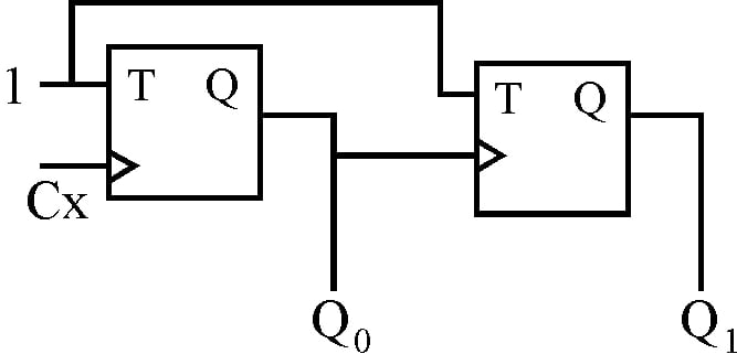
What are the final values of Q1 and Q0 after 4 clock cycles, if initial values are 00 in the sequential circuit shown below?
Answer: D. 00 — Concept — a T flip-flop with T = 1 complements its stored bit on every active clock edge, and holds that bit unchanged when T = 0. Cascading toggle stages so…
- A.
11
- B.
10
- C.
01
- D.
00
Attempted by 23 students.
Show answer & explanation
Correct answer: D
Concept — a T flip-flop with T = 1 complements its stored bit on every active clock edge, and holds that bit unchanged when T = 0. Cascading toggle stages so that each stage takes its clock from the output of the stage before it halves the switching rate at every stage, which makes a chain of n such stages a modulo-2n counter: its state pattern repeats after every 2n active edges of the input clock, whatever state it started from.
Application to this circuit — both T inputs are wired to the constant logic 1, so each flip-flop toggles whenever it receives an active clock edge. Stage 0 takes its clock from Cx, so Q0 changes on every Cx pulse, while stage 1 takes its clock from Q0, so Q1 changes only when Q0 itself supplies an active edge. Writing the state as Q1Q0, starting from 00 and using the rising-edge symbols drawn on both stages:
Pulse 1: Q0 toggles from 0 to 1. That 0-to-1 transition is a rising edge on the clock input of stage 1, so Q1 toggles from 0 to 1 and the state becomes Q1Q0 = 11.
Pulse 2: Q0 toggles from 1 to 0. A falling transition does not trigger a rising-edge stage, so Q1 holds at 1 and the state becomes Q1Q0 = 10.
Pulse 3: Q0 toggles from 0 to 1, which again clocks stage 1, so Q1 toggles from 1 to 0 and the state becomes Q1Q0 = 01.
Pulse 4: Q0 toggles from 1 to 0, stage 1 receives no rising edge and holds its bit, so the state becomes Q1Q0 = 00.
Cross-check — counting toggles gives the same result without tracing edges. Stage 0 sees all 4 clock pulses and complements itself 4 times, an even count, which returns Q0 to 0; stage 1 is clocked twice during those 4 pulses and complements itself twice, again an even count, which returns Q1 to 0. This also shows why the edge polarity is not load-bearing: two toggle stages form a modulo-4 counter whose 4 states make one closed cycle, so 4 pulses always bring the circuit back to the state it started from. With falling-edge stages the intermediate order would run 01, 10, 11, and the state after the fourth pulse would still be the same.
So after 4 clock cycles the circuit has completed one full cycle and is back at its starting state, with Q1 = 0 and Q0 = 0.