Identify the logic function performed by the circuit shown
2005
Identify the logic function performed by the circuit shown
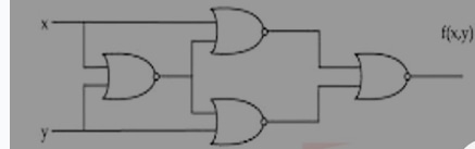
- A.
Exclusive-OR
- B.
AND
- C.
Exclusive-NOR
- D.
NOR
Attempted by 142 students.
Show answer & explanation
Correct answer: C
Based on the logic gates provided in the image, all four gates are NOR gates. This specific configuration is a classic standard implementation.
The logic function performed by this circuit is XNOR (Exclusive-NOR).
Step-by-Step Derivation
Let's break down the output of each gate step-by-step:
First Gate (Left): Takes inputs x and y. Its output is:
$$\text{Output}_1 = \overline{x + y}$$
Top Gate (Middle): Takes input x and the output of the first gate ({x + y}'). Its output is:
$$\text{Output}_2 = \overline{x + \overline{x + y}}$$
Using Boolean algebra (or De Morgan's laws):
$$\text{Output}_2 = \bar{x} \cdot \overline{\overline{x + y}} = \bar{x}(x + y) = \bar{x}x + \bar{x}y = \bar{x}y$$
Bottom Gate (Middle): Takes input y and the output of the first gate ( {x + y}'). Its output is:
$$\text{Output}_3 = \overline{y + \overline{x + y}}$$
Using De Morgan's laws:
$$\text{Output}_3 = \bar{y} \cdot \overline{\overline{x + y}} = \bar{y}(x + y) = \bar{y}x + \bar{y}y = x\bar{y}$$
Final Gate (Right): Takes the outputs of the top and bottom middle gates as its inputs. Its output f(x,y) is:
$$f(x,y) = \overline{\text{Output}_2 + \text{Output}_3} = \overline{\bar{x}y + x\bar{y}}$$
Conclusion
The expression inside the inversion (x'y + xy') represents the XOR gate operation.
Because of the final inversion bar over the whole expression, it becomes the inverse of XOR:
$$f(x,y) = \overline{x \oplus y} = x \odot y$$
Therefore, the circuit performs the XNOR function.