The logic expression for the output of the circuit shown in the figure is
2010
The logic expression for the output of the circuit shown in the figure is
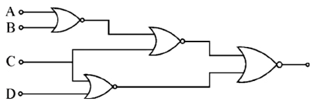
- A.
A̅C̅ + B̅C̅ + CD
- B.
AC̅ + BC̅ + C̅D
- C.
ABC + C̅D̅
- D.
A̅B̅ + BC̅ + C̅D
- E.
None
Attempted by 34 students.
Show answer & explanation
Correct answer: E
The circuit consists of four NOR gates. The top gate outputs A+B complement, which feeds into a second NOR gate with input C to produce C + (A+B) complement. The bottom gate processes C and D to yield C+D complement. The final NOR gate combines these signals, simplifying via De Morgan's laws to C + A'B'D. None of the provided algebraic options match this derived expression.
A video solution is available for this question — log in and enroll to watch it.