Consider the process details given in the following table. A new pre-emptive…
2017
Consider the process details given in the following table.
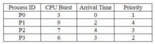
A new pre-emptive scheduling algorithm is proposed, i.e., the Longest Remaining Time Next (LRTN), wherein ties are broken by giving priority to the process with the highest priority. Calculate the following:
i) Turnaround time for Process P2
ii) Response time for Process P3
Answer: A. (i) 20, (ii) 3 — Concept. LRTN (Longest Remaining Time Next) is the pre-emptive counterpart of Longest Job First: at every clock tick the scheduler compares the remaining…
- A.
(i) 20, (ii) 3
- B.
(i) 19, (ii) 3
- C.
(i) 19, (ii) 8
- D.
(i) 20, (ii) 7
Attempted by 212 students.
Show answer & explanation
Correct answer: A
Concept. LRTN (Longest Remaining Time Next) is the pre-emptive counterpart of Longest Job First: at every clock tick the scheduler compares the remaining burst time of every ready (arrived, unfinished) process and runs whichever one currently has the
largest remaining burst time. Because every process's remaining time keeps shrinking as it executes, this comparison must be redone at every time unit — not only when a process arrives or completes — so the process holding the CPU can change even between arrivals. When two or more ready processes tie on remaining time, the tie is broken in favour of the process with the better (numerically smaller) priority value — the question fixes the priority order as 1 > 2 > 3 > 4.
Application. The given process data is:
Process | CPU Burst (BT) | Arrival Time (AT) | Priority |
|---|---|---|---|
P0 | 3 | 0 | 1 |
P1 | 9 | 2 | 4 |
P2 | 7 | 4 | 3 |
P3 | 6 | 3 | 2 |
Tracing every arrival/completion decision point unit by unit (re-checking the tie-break rule whenever two or more remaining times are equal) gives this pre-emptive schedule:
Time Interval | Process Running |
|---|---|
0 – 2 | P0 |
2 – 4 | P1 |
4 – 5 | P2 |
5 – 6 | P1 |
6 – 7 | P3 |
7 – 8 | P2 |
8 – 9 | P1 |
9 – 10 | P3 |
10 – 11 | P2 |
11 – 12 | P1 |
12 – 13 | P3 |
13 – 14 | P2 |
14 – 15 | P1 |
15 – 16 | P3 |
16 – 17 | P2 |
17 – 18 | P1 |
18 – 19 | P3 |
19 – 20 | P2 |
20 – 21 | P1 |
21 – 22 | P0 |
22 – 23 | P3 |
23 – 24 | P2 |
24 – 25 | P1 |
Reading the completion time (CT) of each process off that trace:
Process | AT | BT | CT | TAT = CT − AT | WT = TAT − BT | RT |
|---|---|---|---|---|---|---|
P0 | 0 | 3 | 22 | 22 | 19 | 0 |
P1 | 2 | 9 | 25 | 23 | 14 | 0 |
P2 | 4 | 7 | 24 | 20 | 13 | 0 |
P3 | 3 | 6 | 23 | 20 | 14 | 3 |
Where TAT = CT − AT, WT = TAT − BT, and RT = (time of the process' first CPU allocation) − AT.
Turnaround time of P2 = CT(P2) − AT(P2) = 24 − 4 = 20
Response time of P3 = (P3's first execution slot, 6) − AT(P3) = 6 − 3 = 3
Cross-check. P0 is already ready at t = 0 and every process is CPU-hungry, so the schedule never idles; the last process finishes at t = 25, which equals the sum of all four burst times (3 + 9 + 7 + 6 = 25) — confirming every time unit in the trace above is accounted for exactly once.
Explore the full course: Iocl Engineers Officers Grade A Paper 2