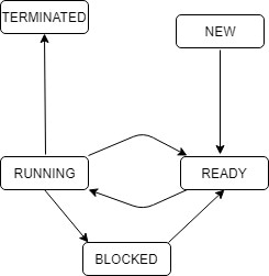
The process state transition diagram in below figure is representative of
1996

The process state transition diagram in below figure is representative of

Untitled
  1. A.

    a batch operating system

  2. B.

    an operating system with a preemptive schedular

  3. C.

    an operating system with a non-preemptive schedular

  4. D.

    a uni-programmed operating system

Attempted by 108 students.

Show answer & explanation

Correct answer: B

The key to answering this question lies in looking at the arrows connecting the RUNNING and READY states:

  • READY -> RUNNING: This occurs when the CPU scheduler selects a process from the ready queue and allocates the CPU to it (Dispatch).

  • RUNNING -> READY: This transition means a process that was actively executing on the CPU is forced to give up the CPU and go back to waiting in the ready queue, even though it has not finished its execution or requested I/O.

An operating system can only force a currently running process to stop executing via preemption (such as a time-slice expiration in Round Robin or a higher-priority process arriving).

In a non-preemptive (or batch) system, once a process gets the CPU, it keeps it until it either terminates or blocks itself for an I/O operation. It never goes straight back to the READY state from the RUNNING state.

Therefore, the presence of the RUNNING -> READY transition directly implies a preemptive scheduler.

Explore the full course: Gate Guidance By Sanchit Sir