The above synchronous sequential circuit built using JK flip-flops is…
2014
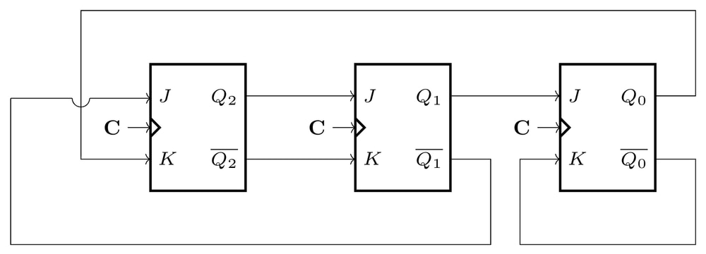
The above synchronous sequential circuit built using JK flip-flops is initialized with \(Q_2Q_1Q_0 = 000\). The state sequence for this circuit for the next 3 clock cycles is
- A.
001, 010, 011
- B.
111, 110, 101
- C.
100, 110, 111
- D.
100, 011, 001
Attempted by 37 students.
Show answer & explanation
Correct answer: C
Key idea: determine each flip-flop's J and K from the feedback, then apply the JK excitation rules (J=K=0: no change; J=1,K=0: set; J=0,K=1: reset; J=K=1: toggle).
From the wiring we get:
J2 = Q0', K2 = Q0
J1 = Q2, K1 = Q2'
J0 = Q1, K0 = Q1'
Now compute the three next states starting from 000:
From 000: Q0=0 so J2=1,K2=0 => Q2 is set (becomes 1). Q2=0 so J1=0,K1=1 => Q1 stays 0. Q1=0 so J0=0,K0=1 => Q0 stays 0. Result: 100.
From 100: Q0=0 so J2=1,K2=0 => Q2 remains 1. Q2=1 so J1=1,K1=0 => Q1 is set (becomes 1). Q1=0 so J0=0,K0=1 => Q0 stays 0. Result: 110.
From 110: Q0=0 so J2=1,K2=0 => Q2 remains 1. Q2=1 so J1=1,K1=0 => Q1 remains 1. Q1=1 so J0=1,K0=0 => Q0 is set (becomes 1). Result: 111.
Therefore the next three states are 100, 110, 111.
A video solution is available for this question — log in and enroll to watch it.