The control signal functions of a 4-bit binary counter are given below (where…
2007
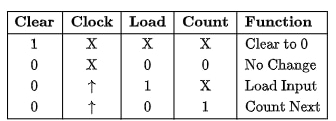
The control signal functions of a 4-bit binary counter are given below (where X is “don’t care”) The counter is connected as follows:
The counter is connected as follows:
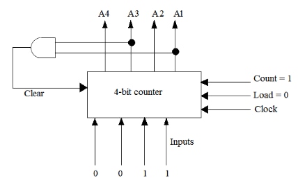
Assume that the counter and gate delays are negligible. If the counter starts at 0, then it cycles through the following sequence:
- A.
0, 3, 4
- B.
0, 3, 4, 5
- C.
0, 1, 2, 3, 4
- D.
0, 1, 2, 3, 4, 5
Attempted by 26 students.
Show answer & explanation
Correct answer: C
Key idea: the control signals determine whether the counter is cleared to 0, loads the parallel inputs, or counts to the next value. From the control table: Clear = 1 forces the counter to 0; when Clear = 0 and Load = 1 on a rising clock the counter loads the parallel inputs; when Clear = 0 and Load = 0 on a rising clock the counter increments (counts next).
Start at 0 (binary 0000). With Count = 1 and Load = 0 the counter increments on each rising clock.
Successive increments produce: 0000 → 0001 (1) → 0010 (2) → 0011 (3) → 0100 (4).
When the counter reaches 0100 (decimal 4), the detection gate monitors the outputs and asserts Clear. Clear = 1 forces the counter back to 0000 on the next event, so the next state after 4 is 0.
The parallel load inputs (0 0 1 1) are not used because Load remains 0 during normal counting in this connection, so no parallel load occurs.
Therefore the observable cycle starting from 0 is: 0, 1, 2, 3, 4.
A video solution is available for this question — log in and enroll to watch it.