Consider the following state diagram and its realization by a JK flip flop The…
2008
Consider the following state diagram and its realization by a JK flip flop
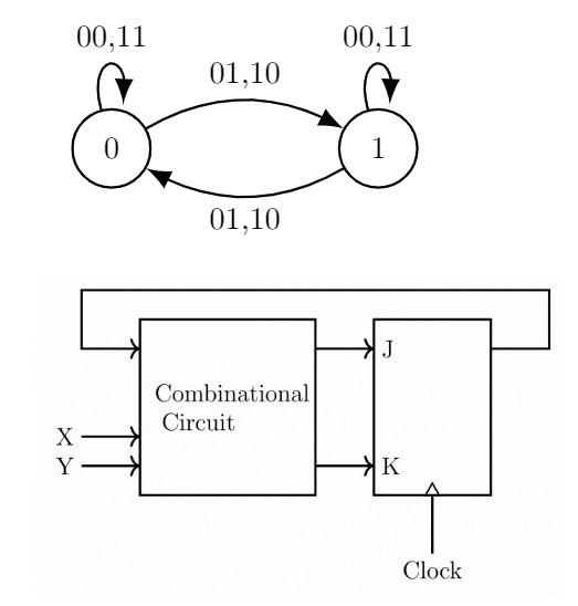
The combinational circuit generates J and K in terms of x, y and Q.
The Boolean expressions for J and K are :
- A.
(x⊕y)' and (x⊕y)'
- B.
(x⊕y)'and x⊕y
- C.
x⊕y and (x⊕y)'
- D.
x⊕y and x⊕y
Attempted by 132 students.
Show answer & explanation
Correct answer: D
Answer: J = x ⊕ y, K = x ⊕ y
Reasoning:
From the state diagram: when inputs x and y are equal (00 or 11) the machine stays in the same state; when x and y differ (01 or 10) the machine moves to the other state.
Thus the next state Q+ equals Q when x = y, and Q+ equals ¬Q when x ≠ y. Using XOR, x ⊕ y = 0 when x = y and x ⊕ y = 1 when x ≠ y, so the desired relation is Q+ = Q ⊕ (x ⊕ y).
Behavior of JK flip-flop: when J = K = 0 it holds (Q+ = Q); when J = K = 1 it toggles (Q+ = ¬Q).
Therefore, set J = K = x ⊕ y so that J = K = 0 when x = y (hold), and J = K = 1 when x ≠ y (toggle). This implements Q+ = Q ⊕ (x ⊕ y) as required.
A video solution is available for this question — log in and enroll to watch it.