Consider the circuit shown in the figure. The Boolean expression F implemented…

GATE · 2017 · EC · Set 2 · Electronics and Communication Engineering

Consider the circuit shown in the figure.
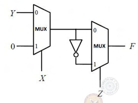
Two cascaded 2-to-1 multiplexers: first selects Y for X=0 and 0 for X=1; second selects first output for Z=0 and its inversion for Z=1.

The Boolean expression F implemented by the circuit is

  1. A.

    X‾ Y‾ Z‾+XY+Y‾Z\overline X\,\overline Y\,\overline Z+XY+\overline Y Z

  2. B.

    X‾YZ‾+XZ+Y‾Z\overline X Y\overline Z+XZ+\overline Y Z

  3. C.

    X‾YZ‾+XY+Y‾Z\overline X Y\overline Z+XY+\overline Y Z

  4. D.

    X‾ Y‾ Z‾+XZ+Y‾Z\overline X\,\overline Y\,\overline Z+XZ+\overline Y Z

Attempted by 11 students.

Sign up free to check your answer

Sign up free

Explore the full course: Gate Guidance By Sanchit Sir

Loading lesson…